Tag: Alexa

  • Custom ESP8266 Home Media Control (w/ Alexa, IR, RF, and Wifi) Pt. 2

    Custom ESP8266 Home Media Control (w/ Alexa, IR, RF, and Wifi) Pt. 2

    Part One

    Github

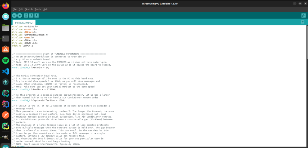
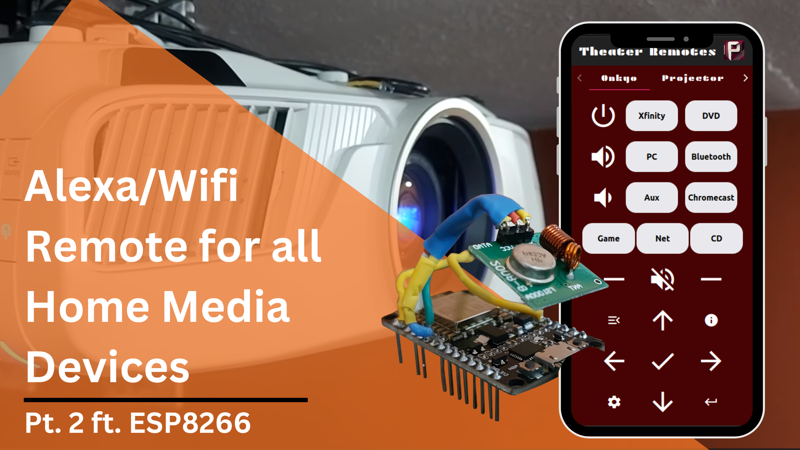
    In this second part, we will be going over the programming and network information for this project to control and automate home media devices using Alexa and IR/RC controllers. If you missed part one, the above link will take you to it. The Arduino files and additional simple examples I use can be found at this Github repository.

    In this specific article, I will be going over my code and setup for the radio-controlled projector screen and the IR-controlled fireplace. I will show how to configure the network so that the ESP8266 controller can be accessed through Alexa or a custom webapp.

    Connect to Wifi

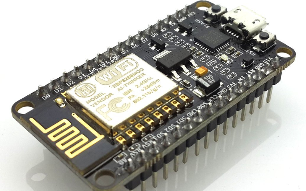
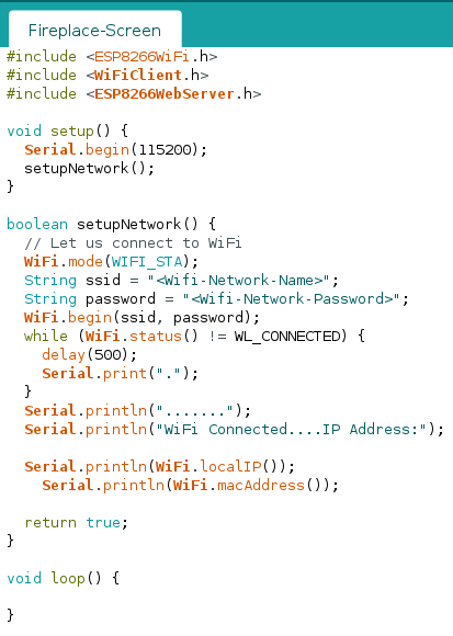
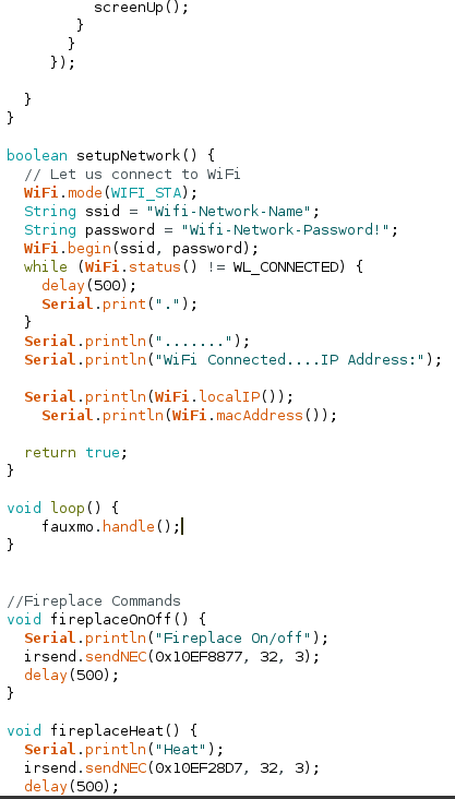
    We first need to configure the Wifi connection for the ESP8266. We can create a function called setupNetwork() like below, being sure to replace the <Wifi-Network-Name> and <Wifi-Network-Password> fields with their respective values.

    Code in arduino IDE

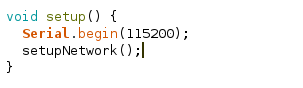
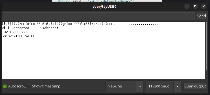
    We will call this function in the setup() function so that when the ESP8266 starts up it will automatically connect to Wifi and print out its IP address to the Serial Monitor. Your code should match below:

    Code in Arduino IDE
    Code in Arduino IDE
    setup()
    The serial monitor for Arduino IDE
    Serial Monitor

    Assign a Static IP

    Next we need to set a static IP for the ESP8266 so that your home router does not change its IP address and cause us to lose connection to it. Go to your router’s gateway page or app and find the DHCP settings.

    Advanced setting in TP-Link router

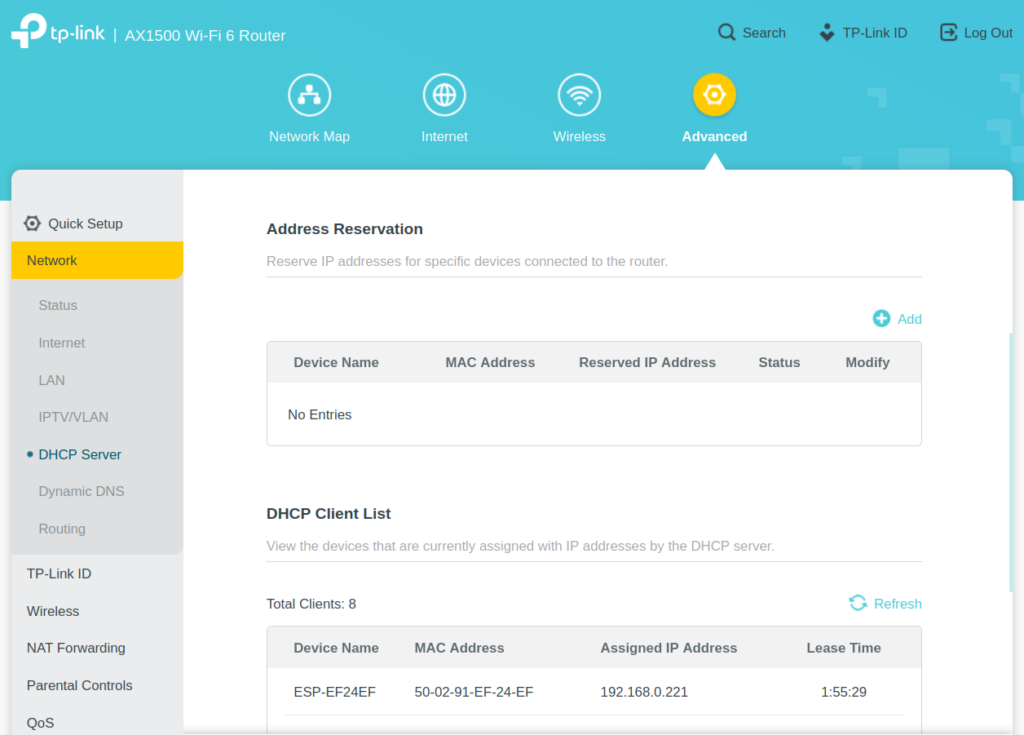
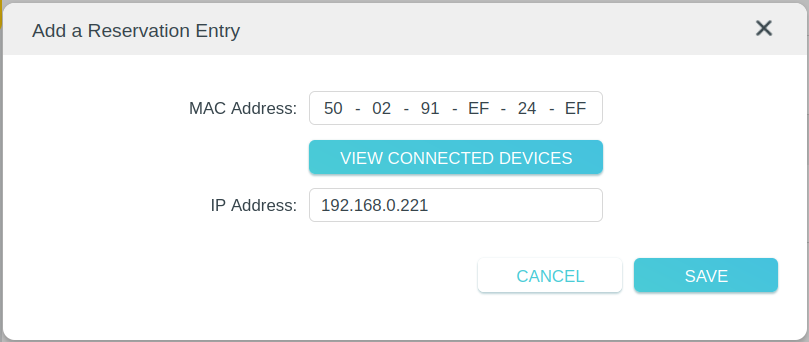
    Find the section for reserving addresses and add a new entry using the ESP8266’s IP Address and Mac Address. This will insure that the Router assigns the same IP address to our ESP8266 every time it connects.

    Router settings for reserving an IP

    Fauxmo

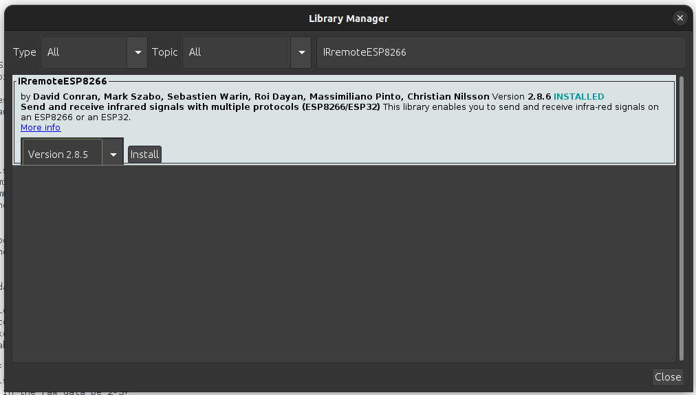
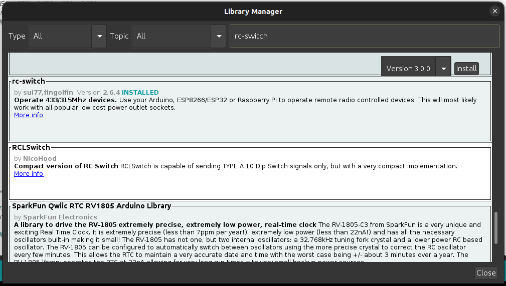
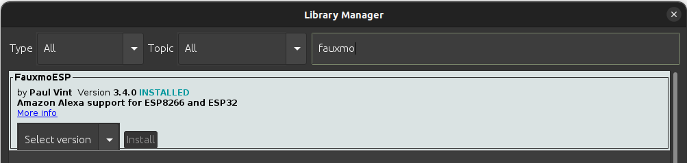
    Install the Fauxmo library using the library manager. Fauxmo will allow us to make a device available on Alexa for turning on or off. It emulates a Wemo device and will look like a smart lightbulb on the Alexa side.

    The library manager in Arduino IDE

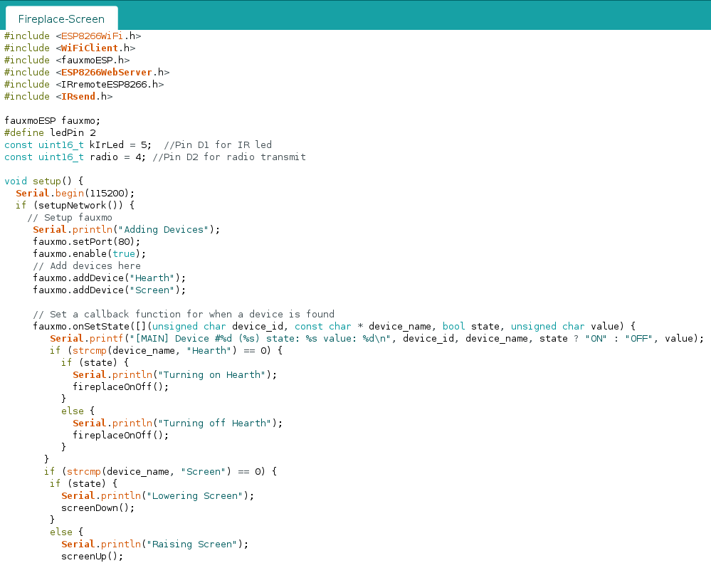
    Add #include <fauxmoESP.h> to the top of your arduino file. Declare a variable: fauxmoESP fauxmoESP. Add the following to the setup() function:

    void setup() { 
      Serial.begin(115200);
      if (setupNetwork()) {
        // Setup fauxmo
         Serial.println("Adding Devices");
         fauxmo.setPort(80);  
         fauxmo.enable(true);
         // Add devices here
         fauxmo.addDevice("Hearth");  
         fauxmo.addDevice("Screen");
    
         // Set a callback function for when a device is found
         fauxmo.onSetState([](unsigned char device_id, const char * device_name, bool state, unsigned char value) {
            Serial.printf("[MAIN] Device #%d (%s) state: %s value: %d\n", device_id, device_name, state ? "ON" : "OFF", value);       
            if (strcmp(device_name, "Hearth") == 0) {
              if (state) {
                Serial.println("Turning on Hearth");
                fireplaceOnOff();
              }
              else {
                Serial.println("Turning off Hearth");
                fireplaceOnOff();
              }
           }
           if (strcmp(device_name, "Screen") == 0) {
            if (state) {
              Serial.println("Lowering Screen");
              screenDown();
            }
            else {
              Serial.println("Raising Screen");
              screenUp();
            }
           }
         }); 
      }
    }
    Code in Arduino IDE
    Code in Arduino IDE

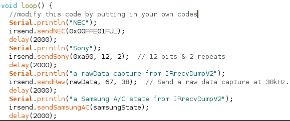
    Make sure to modify the loop() function to have fauxmo.handle(). Also add in your functions for sending IR/RC commands to your devices. Part 1 goes over how to make these commands. These will be used as callback functions for fauxmo to turn on or off our devices. The complete code can be found at this link. Deploy this to your ESP8266 and it will be ready for configuration in the Amazon Alexa app.

    Configuring in Alexa

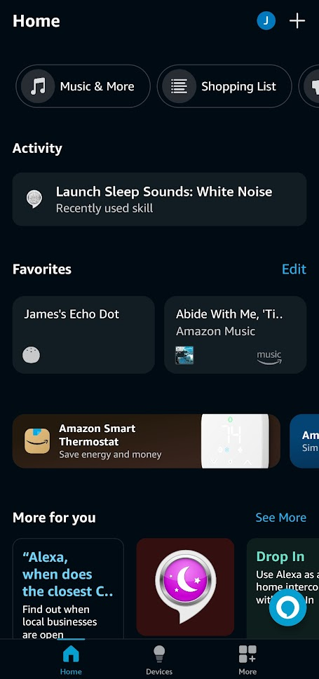
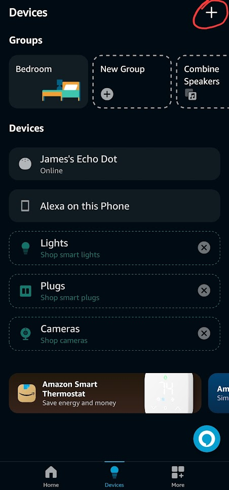
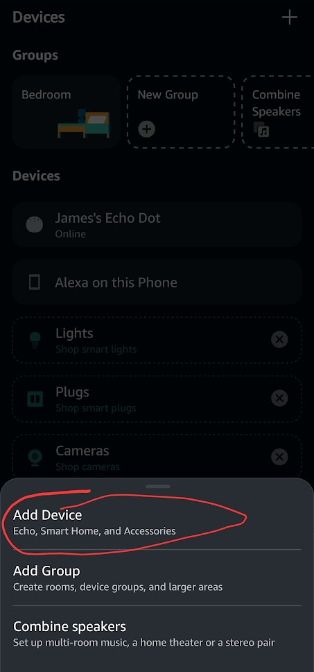
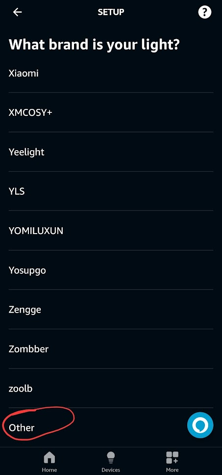
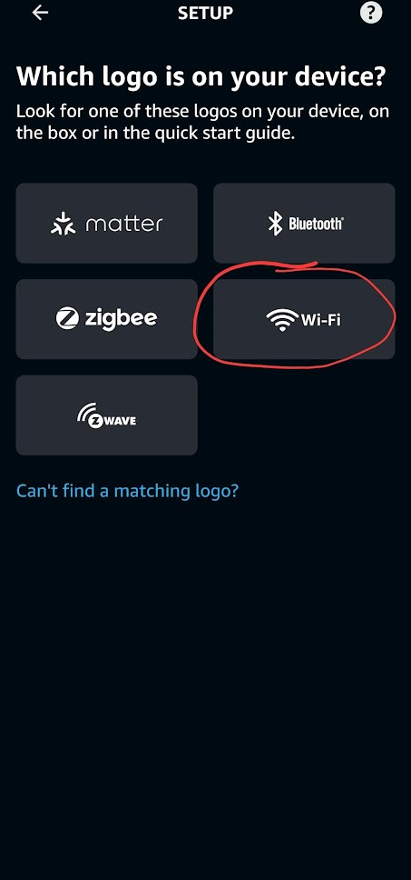
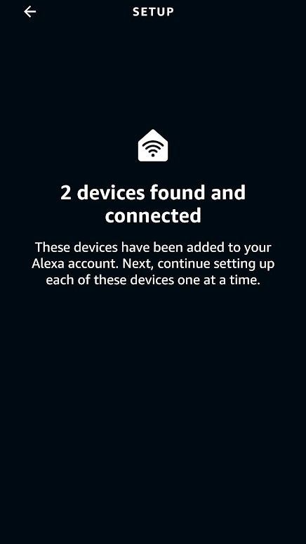
    Setting up in Alexa is extremely easy. Once the sketch is deployed to the ESP8266 and the ESP8266 is running fauxmo, it will appear as a smart light when Alexa scans the network for devices. You can ask Alexa to add a device and it will automatically find it or you can follow the screenshots below from the Alexa app.

    The alexa app
    1
    The Alexa app with the plus icon circled
    2
    The Alexa app with Add Device circled
    3
    The Alexa app with light circled
    4
    The Alexa app with other circled
    5
    The alexa app with wifi logo circled
    6
    The Alexa app discover devices page
    7
    The Alexa app doing a search for new devices
    8
    The Alexa app finding two devices
    9
    The Alexa App
    10

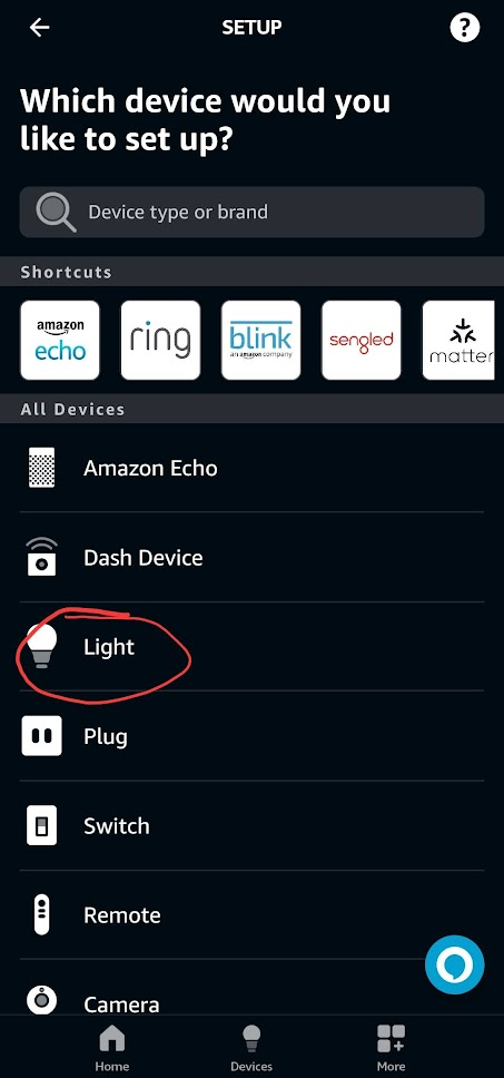
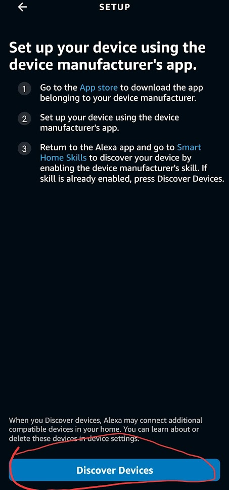
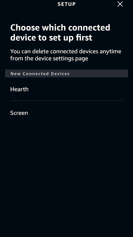
    At this point you should be able to ask Alexa to turn on and off your devices successfully. The name of the devices will be the same as the name in the argument to fauxmo.addDevice(“Name”);

    Creating a Rest API

    The last step in setting up our home media devices is mapping all the different IR/RC commands to endpoints that can be called through network requests.

    In the simple example file for sending IR signals, there are three important parts for setting up the Rest API. The first is the routeServer() function in which we will define the endpoints that can be called.

    //Server Routing
    
    void routeServer () {
      // Define a default response to the server w/o path
      server.on("/", HTTP_GET, []() {
            server.send(200, F("text/html"),
                F("ESP8266 Controller Basement"));
        });
      
      // Create endpoints and connect them to corresponding functions
      server.on("/rcDeviceOn", HTTP_GET, RCDeviceOn);
      server.on("/rcDeviceOff", HTTP_GET, RCDeviceOff);
      server.on("/rcDeviceStop", HTTP_GET, RCDeviceStop);
    
    // If endpoint called that doesn't exist, call handleNotFound()
      server.onNotFound(handleNotFound);
    }

    Each server.on(“/path”, Method, Function) defines an endpoint that can be called with an https request to serveraddress:port/path.

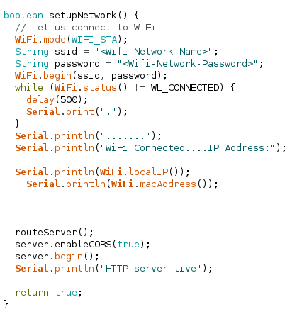
    The next important function is setupNetwork() where we previously set up the wifi connection. We need to add a call to routeServer(), enable CORS, and start the server.

    boolean setupNetwork() {
      // Let us connect to WiFi
      WiFi.mode(WIFI_STA);
      String ssid = "<Wifi-Network-Name>";
      String password = "<Wifi-Network-Password>";
      WiFi.begin(ssid, password);
      while (WiFi.status() != WL_CONNECTED) {
        delay(500);
        Serial.print(".");
      }
      Serial.println(".......");
      Serial.println("WiFi Connected....IP Address:");
    
      Serial.println(WiFi.localIP());
        Serial.println(WiFi.macAddress());
    
      
      // call the routeServer()
      routeServer();
      // enable CORS
      server.enableCORS(true);
     // start the server
      server.begin();
      Serial.println("HTTP server live");
      
      return true;
    }

    The third function is handleNotFound() which is called when an endpoint that doesn’t exist receives a request. It simply sends back to the requesting client a 404: Not Found error.

    void handleNotFound()
    {
        if (server.method() == HTTP_OPTIONS)
        {
            server.sendHeader("Access-Control-Allow-Origin", "*");
            server.sendHeader("Access-Control-Max-Age", "10000");
            server.sendHeader("Access-Control-Allow-Methods", "PUT,POST,GET,OPTIONS");
            server.sendHeader("Access-Control-Allow-Headers", "*");
            server.send(204);
        }
        else
        {
            server.send(404, "text/plain", "");
        }
    }

    Lastly, to get the server actually going we need to #include <ESP8266WebServer.h> at the top and declare a server variable on port 81

     ESP8266WebServer server(81);

    We should also have a function like this to handle requests to the server and fauxmo

    void loop() {
      fauxmo.handle();
      server.handleClient();
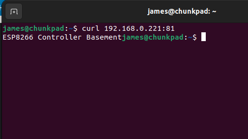
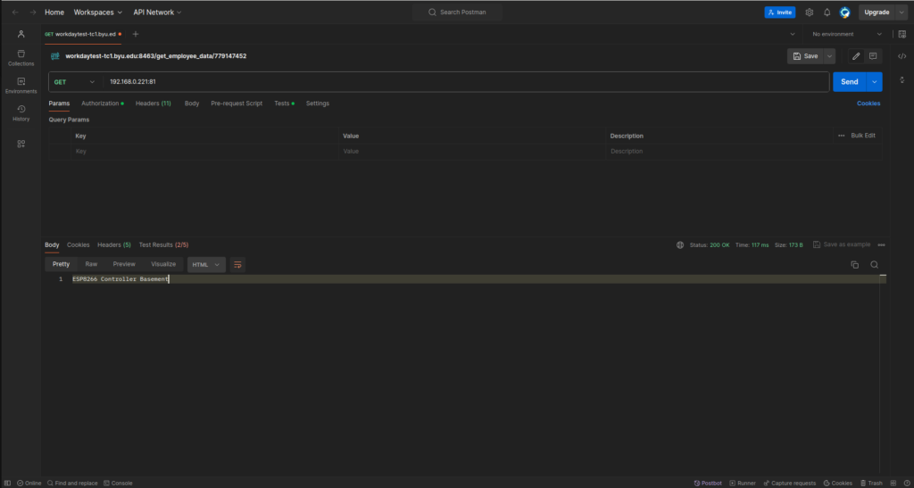
    }

    Deploy to the ESP8266 and you should now be able to send requests to your server. If your ip address was 192.168.0.221 and you set the port to 81, you should be able to use the terminal or software like Postman to test your server’s endpoints.

    Terminal
    Terminal
    Postman
    Postman

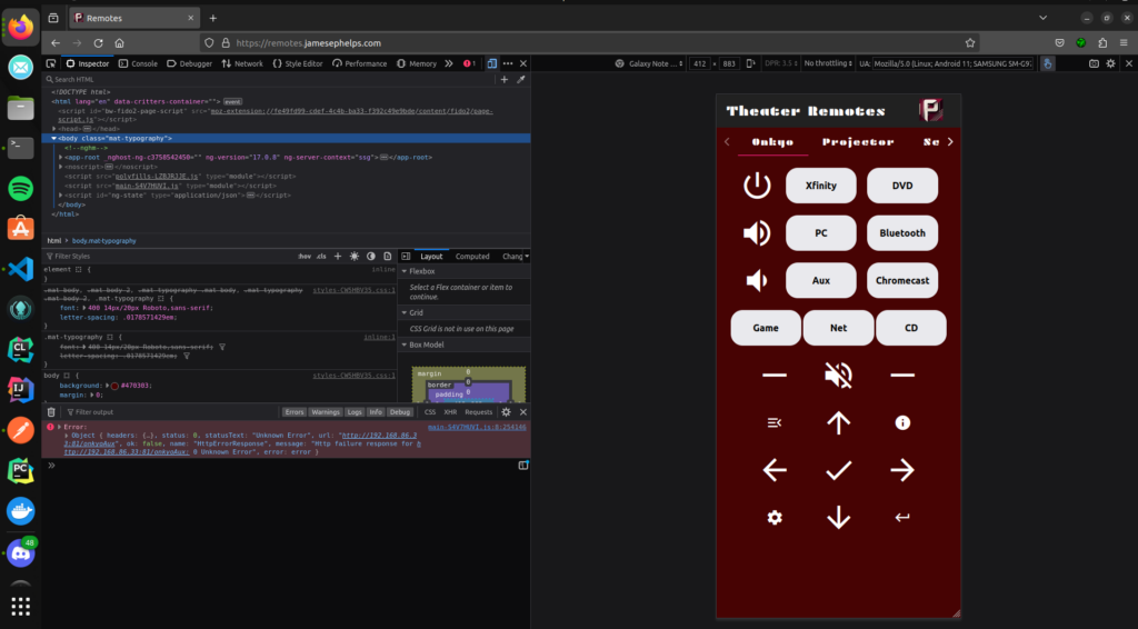
    Calling from a Webapp

    For my use case, I created an angular app that basically consisted of buttons like a remote. When clicked they would call the endpoints on the ESP8266, thus sending the corresponding IR/RC signals to control whatever media device. The webapp runs on an old laptop connected to the home network. The interface of the webapp can be viewed at remotes.jamesephelps.com.

    Each button calls a function like this one below to send requests to the ESP8266

     deviceOnOff(): void {
        const url = 'http://192.168.0.23:81/deviceOn';
        this.httpClient.get(url).subscribe(
          (data) => {
            console.log('Response:', data);
          },
          (error) => {
            console.error('Error:', error);
          }
        );
      }
    Webapp in a browser
    The webapp in a browser
  • Custom ESP8266 Home Media Control (w/ Alexa, IR, RF, and Wifi) Pt. 1

    Custom ESP8266 Home Media Control (w/ Alexa, IR, RF, and Wifi) Pt. 1

    In this series of articles I will be going over my efforts to create a home media control system using a couple ESP8266’s. The end result will be a fully automated theater setup through Amazon Alexa and a webapp built in Angular. This series will go over setting up an ESP8266 to read and transmit both IR signal and RF signals, making controllable smart devices for Alexa, creating a locally hosted webapp for remote control, and the steps to properly configure a home network.

    The following video shows the end result using Alexa to turn on all devices in the home theater. This setup includes a video streaming box, surround system, projector, radio-controlled projector screen, and an electric fireplace. The specific device information is listed under the video.

    For this project, I will be using Nodemcu ESP8266 Development Boards that I purchased off of Amazon. These can be found for cheaper from websites that ship from China, but I was on a time limit since I will be returning back to school soon, so I went the faster Amazon route. I specifically used the HiLetGo models which seemed to work. Of the three I bought, one arrived dead, but the other two were fine.

    The ESP8266 is a microcontroller that can be easily programmed through a micro usb connection using an IDE like Arduino. The ESP8266 is special because it has wifi capabilities and a very strong community behind it, making resources for it readily available on the internet.

    In addition to the boards, I also purchased an IR Receiver and LED from Adafruit. These will allow us to read Infrared signals from the remotes and then be able to replicate them ourselves on our ESP8266 to emit the same signals as our remotes. I also got a tiny breadboard from Adafruit to allow for easier prototyping before I permanently soldered components to the ESP8266’s.

    Lastly, I also ended up needing to get a 433 MHz RF receiver and transmitter for the projector screen. The projector screen is controlled by an RF remote which emits radio signals. When searching for such a receiver and transmitter, I found many transmitters that seemed to be missing a coil on Amazon as shown below.

    What effect this has is outside of the scope of my knowledge, but several reviewers indicated the coil is necessary for proper functioning, so I was sure to buy one with the coil. For me, all the product listings when I first searched on Amazon were missing this coil. I had to search for a while before I found one that seemed to actually have the coil.

    Most devices are controlled using IR remotes which emit an IR signal that the device can pick up on using a receiver. To get our needed signals, we will connect the IR receiver to our ESP8266 board and then record data that it picks up from our remotes. We will use a library called IRremoteESP8266 that can be found in the Arduino libraries to understand the data that the receiver picks up.

    In Arduino, go to Tools>Manage Libraries… (Ctrl+shift+I). Search for “IRremoteESP8266” and install the only one that pops up.

    Now go to your file manager and find where Arduino is installed. From there go to libraries/IRremoteESP8266/examples/IRrecDumpv2 and open in Arduino the IRrecDumpv2.ino file.

    This sketch allows us to receive codes from the remotes on the ESP8266. The top section has a couple of parameters you can edit to fine tune your setup. It is likely you will not need to modify this at all. For mine to work, I had to change kMinUnknownSize to a very high number, because I was picking up random numbers on my receiver.

    Deploy this sketch to your ESP8266 by pressing the arrow up in the top left. This will pop up a terminal, displaying the status of the compiling process and then the write process. Now we need to actually connect the IR receiver to our ESP8266.

    I was able to use the breadboard and just plug the receiver in since this is a super simple setup. Once the receiver is connected, keep the board connected to the computer, and open the serial monitor in Arduino.

    I had to put the remote pretty close to my receiver for it to pick it up for some reason

    If successful, each time you press a button, output should show up in the serial monitor that looks like this:

    Timestamp : 000740.274
    Library   : v2.8.6
    
    Protocol  : NEC
    Code      : 0x10EF8877 (32 Bits)
    uint16_t rawData[71] = {9078, 4478,  598, 560,  574, 558,  574, 558,  574, 1686,  572, 560,  572, 562,  572, 558,  574, 558,  576, 1686,  570, 1692,  576, 1686,  570, 562,  572, 1690,  576, 1686,  572, 1690,  576, 1684,  572, 1690,  578, 554,  568, 564,  570, 562,  572, 1690,  576, 556,  576, 554,  580, 554,  568, 564,  570, 1694,  574, 1686,  570, 1692,  576, 556,  576, 1686,  572, 1692,  576, 1686,  570, 39392,  9082, 2240,  600};  // NEC 10EF8877
    uint32_t address = 0x8;
    uint32_t command = 0x11;
    uint64_t data = 0x10EF8877;

    Go through each button on the remote that you want and record what it outputs to the serial monitor. We will use the code (ex. 0x10EF8877), the protocol (ex. NEC), and the amount of bits (ex. 32 Bits) when we send a signal to the remote. Later when we write the code to send the signals it will be done similar to this this:

    // NEC Protocol
    irsend.sendNEC(0x10EF8877, 32, 2);
    // Epson Protocol
    irsend.sendEpson(0x4BB641BE, 32, 2);
    

    I keep getting code 0xFFFFFF in the serial monitor

    I am only getting question marks in the serial monitor

    I am just getting continuous random output in the serial monitor

    Sending IR Signals

    To send the signals that we recorded, we must first wire the IR Led up to our ESP8266. The following diagram shows the proper way to connect the Led to the board.

    This should be pretty easy using a breadboard and some wires. To test if your remote signals work, navigate back to your Arduino folder like previously and go through the folders: libraries/IRremoteESP8266/examples/IRsendDemo and open the IRsendDemo.ino file. If you followed the diagram above, you will need to change kIrLed variable to 5. Now, put your own codes in the loop() so that your ESP8266 will continuously send your signals so we can test them. Deploy this new sketch to your board.

    If you want to check if your board is sending any IR signals at all, you can look at the IR led through your phone’s camera. If it is working, you will see distinct purple flashes. If you have the correct codes, it will now be able to interact with your controllable devices just like your original remote does.

    Receiving RF signals

    If you have a device that is radio controlled by 433MHz, we can use the rc-switch library to decode and transmit radio signals. Go back to the library manager (Ctrl+shift+I) in Arduino and search for rc-switch to install. Make sure to install the one by sui77 and fingolfin.

    Next, go to the Arduino folder and navigate through the following folders libraries/rc-switch/examples/ReceiveDemo_Simple/ and open ReceiveDemo_Simple.ino. This sketch allows us to use the RF receiver to get codes that represent the radio signals from our RF remotes. Deploy this sketch to the board. (You may need to adjust the baudrate if you are using a different rate. This is done in the code at Serial.begin(9600) where 9600 is the baudrate) Now, wire up the receiver as shown in this diagram.

    If done correctly, you should now be able to press buttons on your RF remote and data will show up in the Serial Monitor. There are three things we’re are looking for: a code, a number of bits, and a protocol number.

    6582737
    24bit
    Protocol: 1

    Transmitting RF Signals

    To test if the RF signals we picked up work, we can use the provided SendDemo.ino file in the folders Arduino/libraries/rc-switch/examples/SendDemo/. If you got the output from the previous example, you would test it by adding a line of code to the loop() function like so:

    void loop() {
      mySwitch.send(6582737, 24); 
      delay(1000); 
    }

    The wiring for the transmitter is done as follows:

    If you are using this same setup, you will need to change the line in the sketch mySwitch.enableTransmit(4); so that it uses pin 4 which is D2. Deploy the sketch and you should now be able to control your RF device using the ESP8266.


    In summary, following these steps, you should be able to get all the data from your remotes and devices that you will need in order to control them. In part 2, we will go over actually doing the programming so that voice assistants like Alexa or a custom webapp can send these signals to the devices.