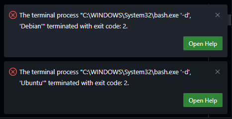
After updating VSCode to May 2025 (v1.101) on Windows, I found that any WSL terminals failed to open. Somehow VSCode was now trying to use “C:\WINDOWS\System32\bash.exe” to run the WSL terminals which was resulting in the following errors:
The terminal process "C:\WINDOWS\System32\bash.exe '-d', 'Debian'" terminated with exit code: 2.
The terminal process "C:\WINDOWS\System32\bash.exe '-d', 'Ubuntu'" terminated with exit code: 2.
The solution is to update the VSCode settings to use the correct WSL executable. The settings are located in the `settings.json` file at C:\Users\<YourUsername>\AppData\Roaming\Code\User\settings.json.
Look for “terminal.integrated.profiles.windows” and if it doesn’t exist, you can add it. If it does exist, ensure that the WSL profile is set to use `wsl.exe` instead of `bash.exe`. Here is the code snippet you need to add or modify in your `settings.json` file:
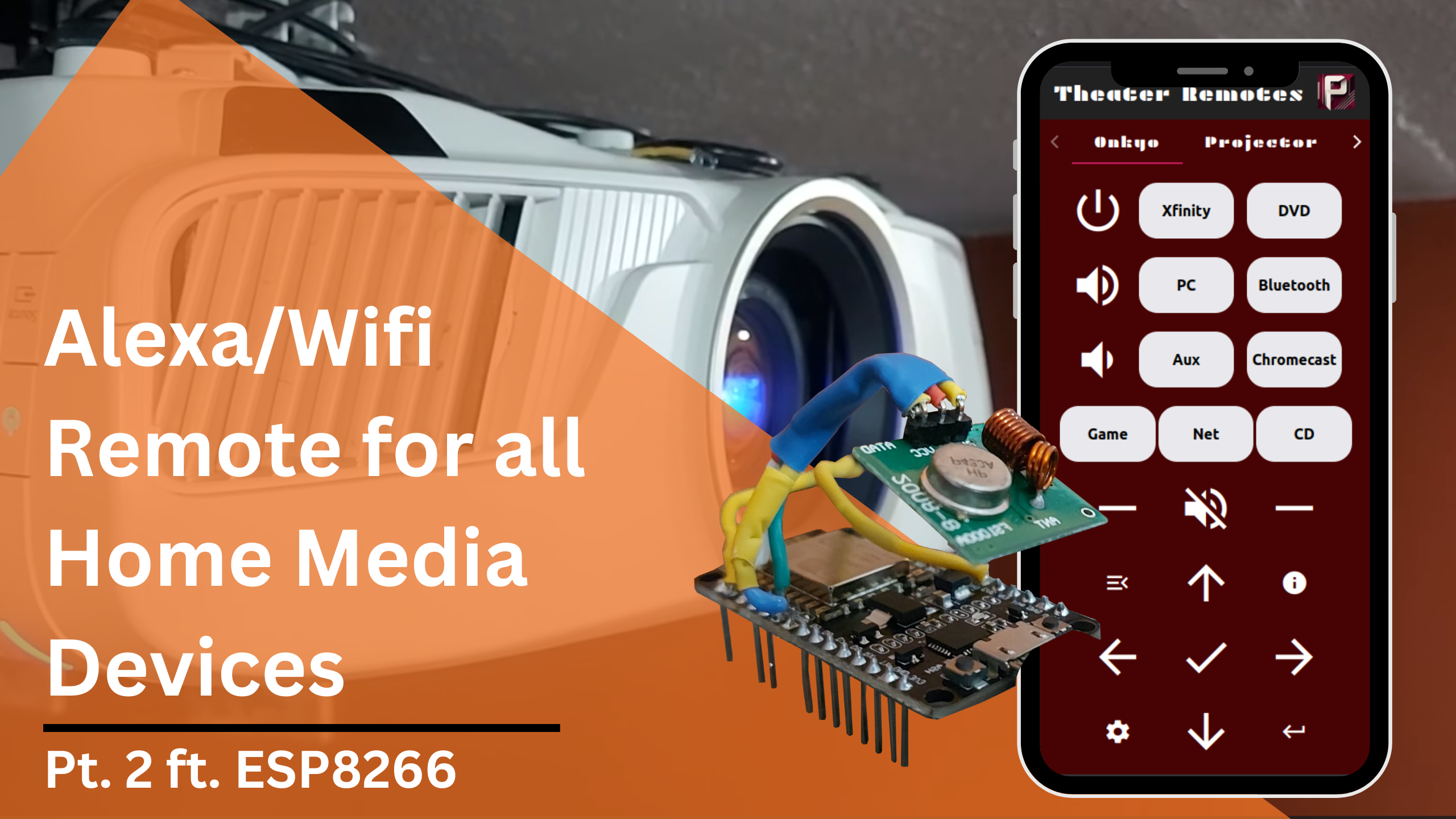
In this second part, we will be going over the programming and network information for this project to control and automate home media devices using Alexa and IR/RC controllers. If you missed part one, the above link will take you to it. The Arduino files and additional simple examples I use can be found at this Github repository.
In this specific article, I will be going over my code and setup for the radio-controlled projector screen and the IR-controlled fireplace. I will show how to configure the network so that the ESP8266 controller can be accessed through Alexa or a custom webapp.
Connect to Wifi
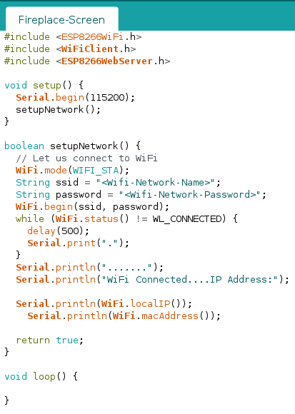
We first need to configure the Wifi connection for the ESP8266. We can create a function called setupNetwork() like below, being sure to replace the <Wifi-Network-Name> and <Wifi-Network-Password> fields with their respective values.
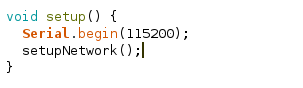
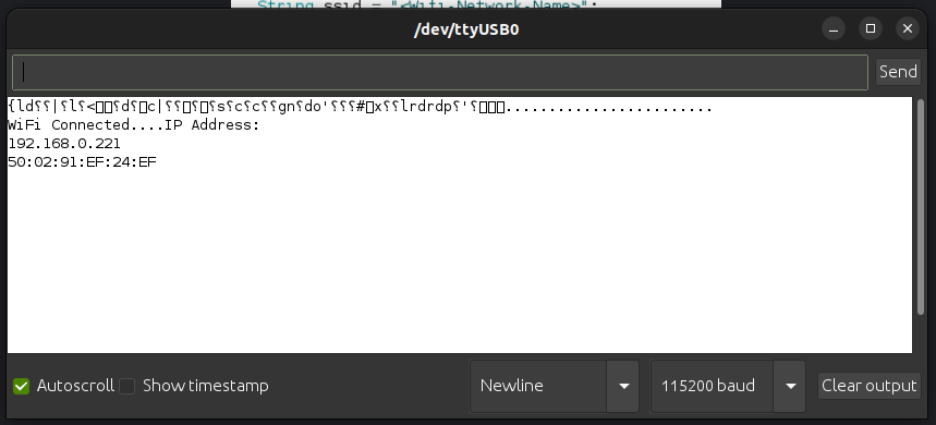
We will call this function in the setup() function so that when the ESP8266 starts up it will automatically connect to Wifi and print out its IP address to the Serial Monitor. Your code should match below:
setup()
Serial Monitor
Assign a Static IP
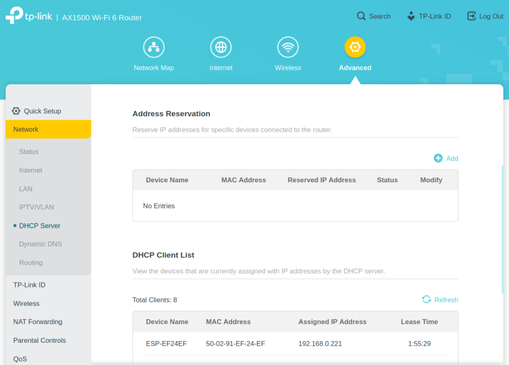
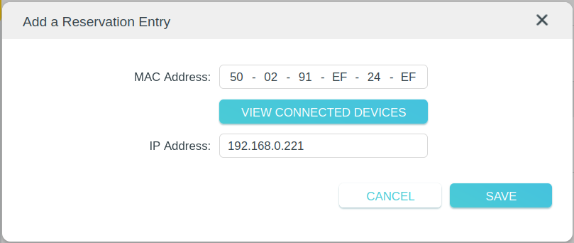
Next we need to set a static IP for the ESP8266 so that your home router does not change its IP address and cause us to lose connection to it. Go to your router’s gateway page or app and find the DHCP settings.
Find the section for reserving addresses and add a new entry using the ESP8266’s IP Address and Mac Address. This will insure that the Router assigns the same IP address to our ESP8266 every time it connects.
Fauxmo
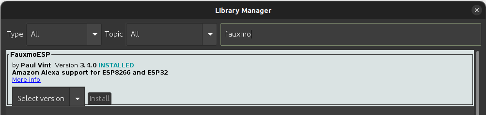
Install the Fauxmo library using the library manager. Fauxmo will allow us to make a device available on Alexa for turning on or off. It emulates a Wemo device and will look like a smart lightbulb on the Alexa side.
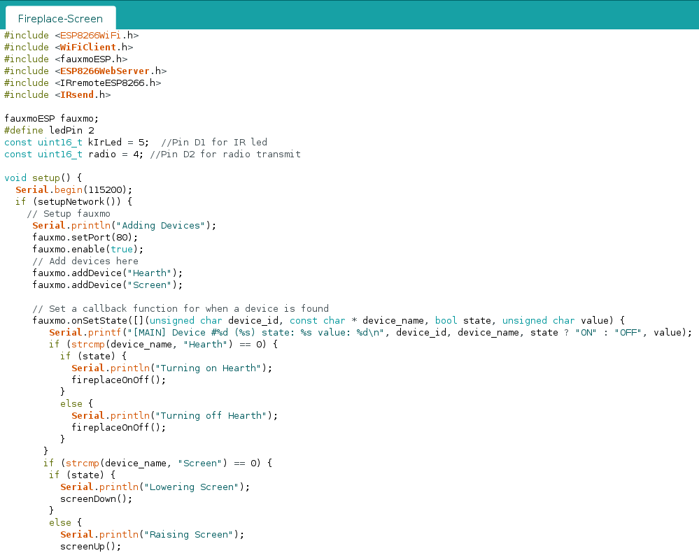
Add #include<fauxmoESP.h> to the top of your arduino file. Declare a variable: fauxmoESP fauxmoESP. Add the following to the setup() function:
void setup() {
Serial.begin(115200);
if (setupNetwork()) {
// Setup fauxmo
Serial.println("Adding Devices");
fauxmo.setPort(80);
fauxmo.enable(true);
// Add devices here
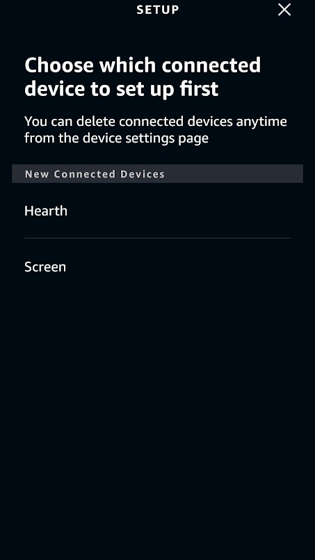
fauxmo.addDevice("Hearth");
fauxmo.addDevice("Screen");
// Set a callback function for when a device is found
fauxmo.onSetState([](unsigned char device_id, const char * device_name, bool state, unsigned char value) {
Serial.printf("[MAIN] Device #%d (%s) state: %s value: %d\n", device_id, device_name, state ? "ON" : "OFF", value);
if (strcmp(device_name, "Hearth") == 0) {
if (state) {
Serial.println("Turning on Hearth");
fireplaceOnOff();
}
else {
Serial.println("Turning off Hearth");
fireplaceOnOff();
}
}
if (strcmp(device_name, "Screen") == 0) {
if (state) {
Serial.println("Lowering Screen");
screenDown();
}
else {
Serial.println("Raising Screen");
screenUp();
}
}
});
}
}
Make sure to modify the loop() function to have fauxmo.handle(). Also add in your functions for sending IR/RC commands to your devices. Part 1 goes over how to make these commands. These will be used as callback functions for fauxmo to turn on or off our devices. The complete code can be found at this link. Deploy this to your ESP8266 and it will be ready for configuration in the Amazon Alexa app.
Configuring in Alexa
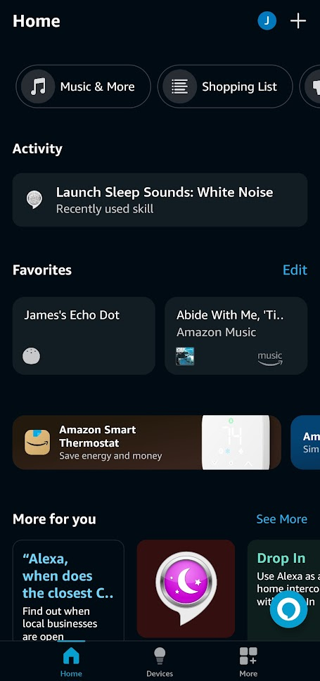
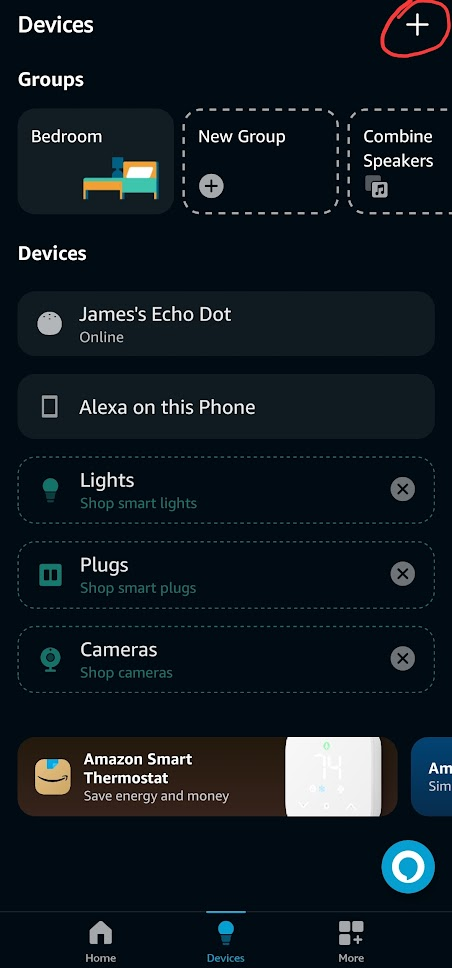
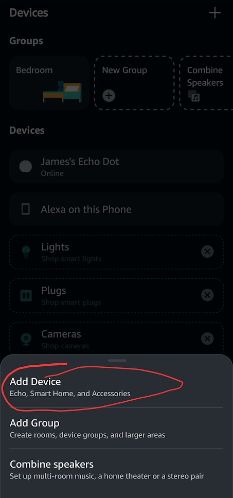
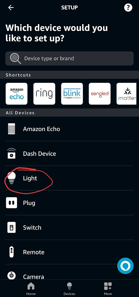
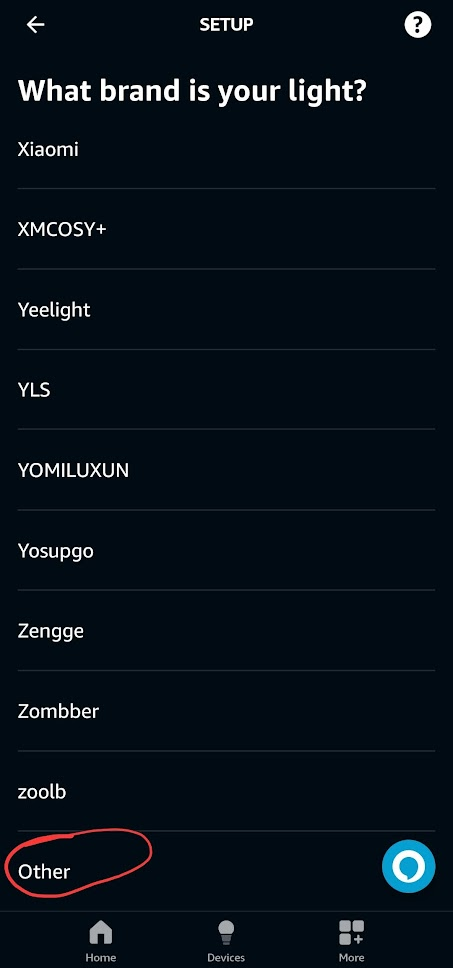
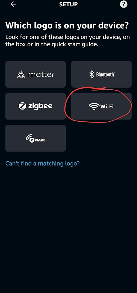
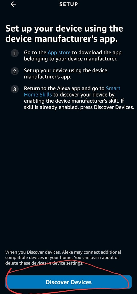
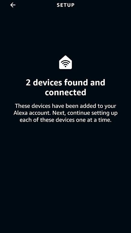
Setting up in Alexa is extremely easy. Once the sketch is deployed to the ESP8266 and the ESP8266 is running fauxmo, it will appear as a smart light when Alexa scans the network for devices. You can ask Alexa to add a device and it will automatically find it or you can follow the screenshots below from the Alexa app.
1
2
3
4
5
6
7
8
9
10
At this point you should be able to ask Alexa to turn on and off your devices successfully. The name of the devices will be the same as the name in the argument to fauxmo.addDevice(“Name”);
Creating a Rest API
The last step in setting up our home media devices is mapping all the different IR/RC commands to endpoints that can be called through network requests.
In the simple example file for sending IR signals, there are three important parts for setting up the Rest API. The first is the routeServer() function in which we will define the endpoints that can be called.
//Server Routing

void routeServer () {
  // Define a default response to the server w/o path
  server.on("/", HTTP_GET, []() {
        server.send(200, F("text/html"),
            F("ESP8266 Controller Basement"));
    });

  // Create endpoints and connect them to corresponding functions
  server.on("/rcDeviceOn", HTTP_GET, RCDeviceOn);
  server.on("/rcDeviceOff", HTTP_GET, RCDeviceOff);
  server.on("/rcDeviceStop", HTTP_GET, RCDeviceStop);

// If endpoint called that doesn't exist, call handleNotFound()
  server.onNotFound(handleNotFound);
}
Each server.on(“/path”, Method, Function) defines an endpoint that can be called with an https request to serveraddress:port/path.
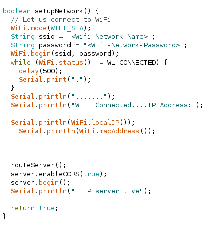
The next important function is setupNetwork() where we previously set up the wifi connection. We need to add a call to routeServer(), enable CORS, and start the server.
boolean setupNetwork() {
// Let us connect to WiFi
WiFi.mode(WIFI_STA);
String ssid = "<Wifi-Network-Name>";
String password = "<Wifi-Network-Password>";
WiFi.begin(ssid, password);
while (WiFi.status() != WL_CONNECTED) {
delay(500);
Serial.print(".");
}
Serial.println(".......");
Serial.println("WiFi Connected....IP Address:");
Serial.println(WiFi.localIP());
Serial.println(WiFi.macAddress());
// call therouteServer()
routeServer();
// enable CORS
server.enableCORS(true);
// start the server
server.begin();
Serial.println("HTTP server live");
return true;
}
The third function is handleNotFound() which is called when an endpoint that doesn’t exist receives a request. It simply sends back to the requesting client a 404: Not Found error.
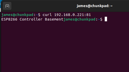
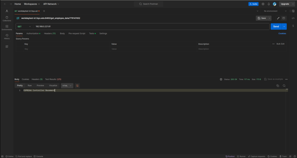
Deploy to the ESP8266 and you should now be able to send requests to your server. If your ip address was 192.168.0.221 and you set the port to 81, you should be able to use the terminal or software like Postman to test your server’s endpoints.
TerminalPostman
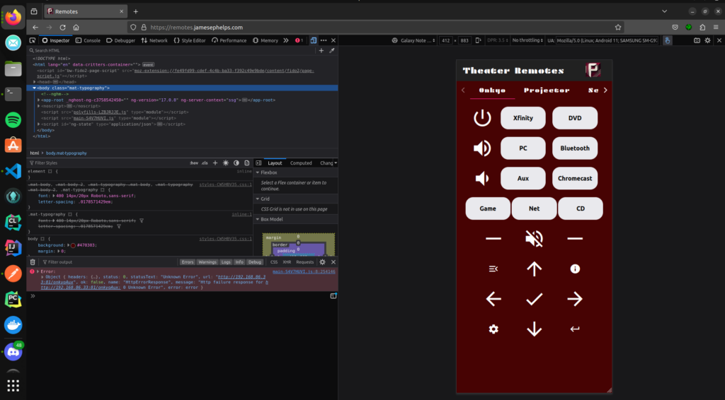
Calling from a Webapp
For my use case, I created an angular app that basically consisted of buttons like a remote. When clicked they would call the endpoints on the ESP8266, thus sending the corresponding IR/RC signals to control whatever media device. The webapp runs on an old laptop connected to the home network. The interface of the webapp can be viewed at remotes.jamesephelps.com.
Each button calls a function like this one below to send requests to the ESP8266
The steps to setting up a development for Garmin IQ in the past for Ubuntu 20+ have had some issues with library dependencies, but these seem to have been cleared up in the recent updates. This article will go over how to easily setup the simulator for Garmin devices in conjunction with VSCode on Ubuntu 22.04.
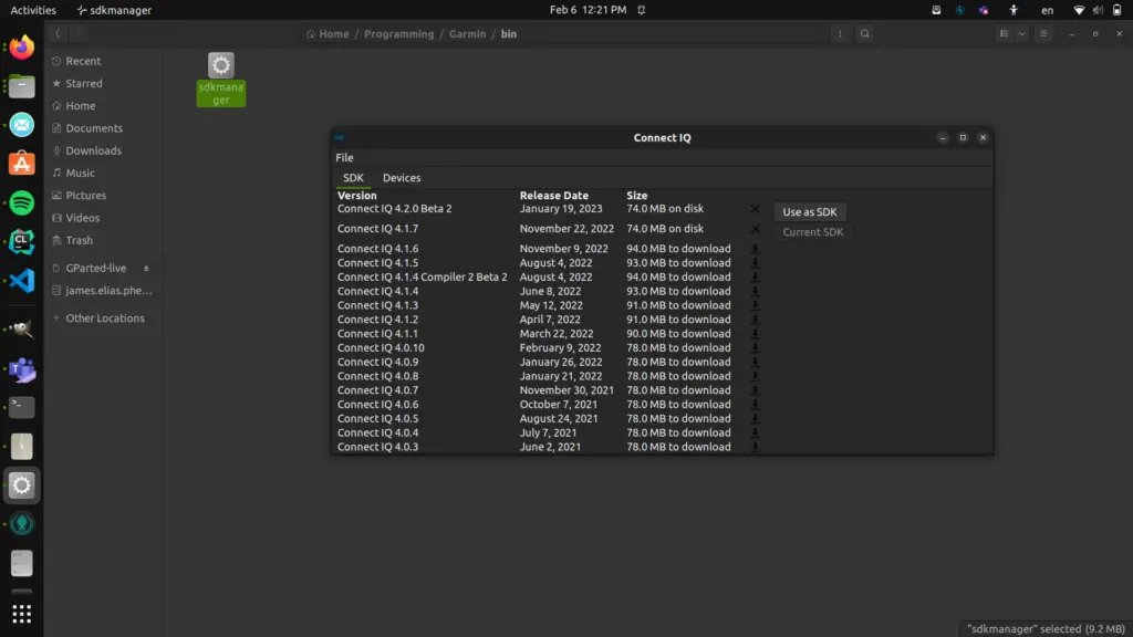
1. Download the SDK
Visit https://developer.garmin.com/connect-iq/sdk/ and read the license agreement. Then accept and download the APK for Linux. It will download a zip file. Extract this to get the bin and share folders. I recommend extracting it to a location outside of your downloads folder so they are not lost later.
Once extracted open the bin folder and double click on the file named ‘sdkmanager.’ This should open a GUI that will download the SDK and devices. If you can not run the executable file you can give it permission to run by right clicking sdkmanager>Poperties>Permission and checking the box next to Execute: Allow Executing File as Program. Or you can navigate to the parent directory in the terminal and use the following command:
sudo chmod +x sdkmanager
Once the GUI opens up click Use as SDK next to one of the SDK options. You may have to drag the window size out to see the option. You can also manage the Garmin devices it downloads in the Devices tab.
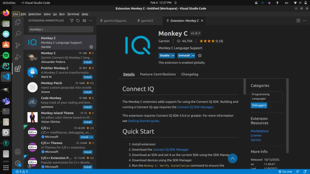
2. Install Monkey C in VSCode
Assuming you have Visual Code Studio installed, open it up and navigate to extensions in the left sidebar. Search for “Monkey C.” Select the option by Garmin and install it.
Monkey C is an object oriented programming language created by Garmin for their IQ Connect ecosystem. You can program watchfaces, apps, widgets, and data fields using it. It is meant to be easy to learn and similar to other familiar programming languages. You can read more about it here and get the documentation.
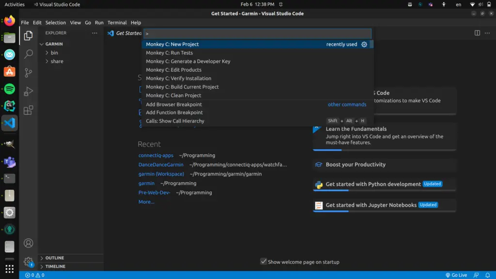
3. Start a Project
Create a folder in which you can store your Monkey C project. Open the folder up in VSCode. Now hit Ctrl+Shift+P. This will open up a command search. Search for the Monkey C: New Project Command.
Follow the prompts to give your project a name, select type as watchface, select simple, and then version 3.0.0. Make sure to put the project in the newly created directory.
You should now have a file structure built with a Resources folder, Source folder, and a manifest.xml file and a monkey.jungle file.
4. Create Developer Key
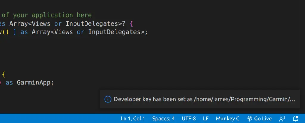
Before we can run the watchface on the simulator, we need to make a developer key. Type Ctrl+Shift+P again to pull up the command search. Search for “Monkey C: Generate a Developer Key.” It should open up a file manager screen from which you can choose a location for your key to be stored.
Once you select the folder it will display a message like the one above in the bottom right of the screen. You are now ready to test run the watchface on the simulator.
5. Run the Watchface on Simulator
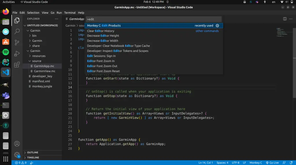
Type Ctrl+Shift+P once again and search for the command “Monkey C: Edit Products.”
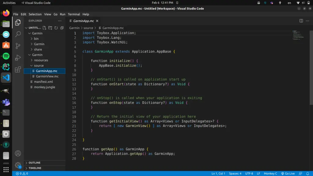
Find a watch model from the resulting drop-down menu and click on the checkbox next to it. This will set it as the target device for use in the simulator. Now navigate to the GarminApp.mc file in the Source folder using the file manager sidebar on the left.
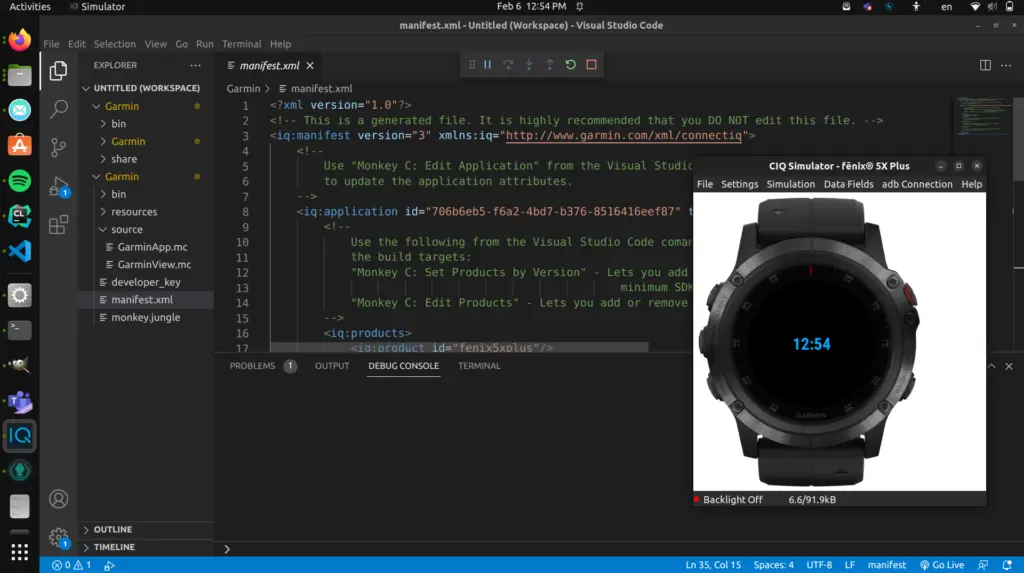
Go to the top and click on Run>Run without Debugging. If all goes well, it should take a few seconds to open the simulator and run the watchface. Your development environment is now all set!