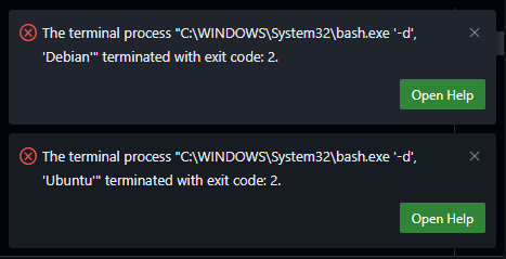
After updating VSCode to May 2025 (v1.101) on Windows, I found that any WSL terminals failed to open. Somehow VSCode was now trying to use “C:\WINDOWS\System32\bash.exe” to run the WSL terminals which was resulting in the following errors:
The terminal process "C:\WINDOWS\System32\bash.exe '-d', 'Debian'" terminated with exit code: 2.
The terminal process "C:\WINDOWS\System32\bash.exe '-d', 'Ubuntu'" terminated with exit code: 2.
The solution is to update the VSCode settings to use the correct WSL executable. The settings are located in the `settings.json` file at C:\Users\<YourUsername>\AppData\Roaming\Code\User\settings.json.
Look for “terminal.integrated.profiles.windows” and if it doesn’t exist, you can add it. If it does exist, ensure that the WSL profile is set to use `wsl.exe` instead of `bash.exe`. Here is the code snippet you need to add or modify in your `settings.json` file:
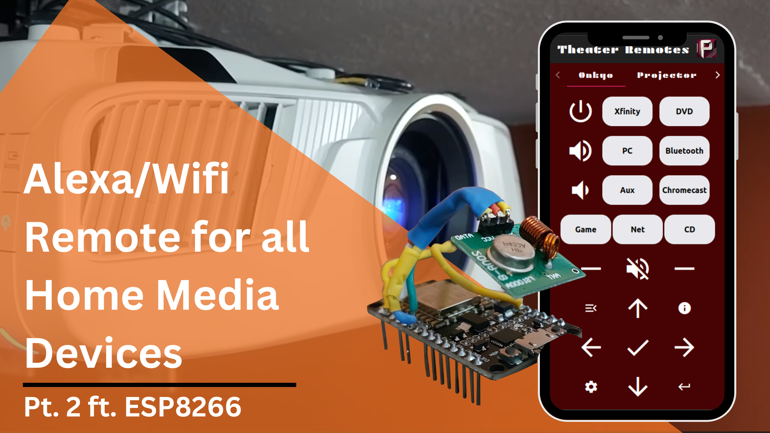
In this second part, we will be going over the programming and network information for this project to control and automate home media devices using Alexa and IR/RC controllers. If you missed part one, the above link will take you to it. The Arduino files and additional simple examples I use can be found at this Github repository.
In this specific article, I will be going over my code and setup for the radio-controlled projector screen and the IR-controlled fireplace. I will show how to configure the network so that the ESP8266 controller can be accessed through Alexa or a custom webapp.
Connect to Wifi
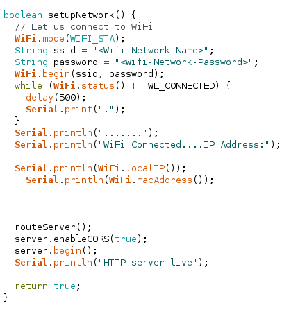
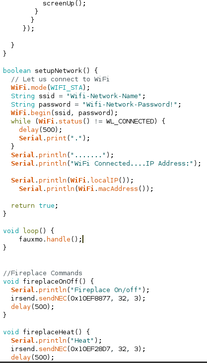
We first need to configure the Wifi connection for the ESP8266. We can create a function called setupNetwork() like below, being sure to replace the <Wifi-Network-Name> and <Wifi-Network-Password> fields with their respective values.
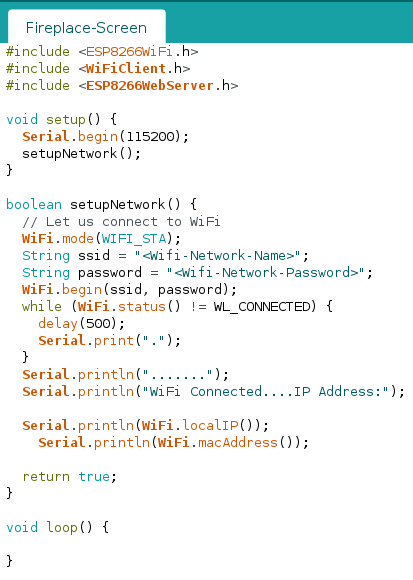
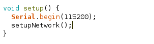
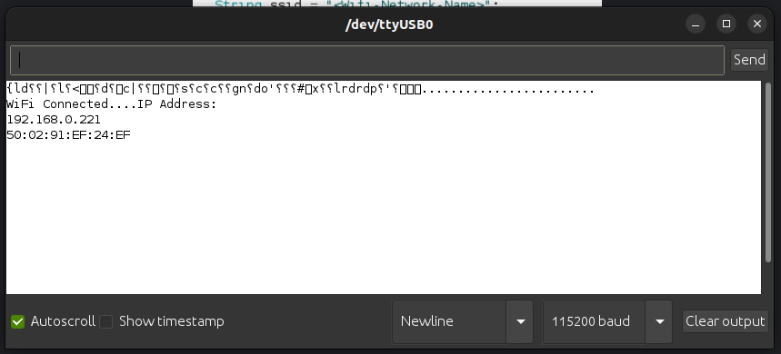
We will call this function in the setup() function so that when the ESP8266 starts up it will automatically connect to Wifi and print out its IP address to the Serial Monitor. Your code should match below:
setup()
Serial Monitor
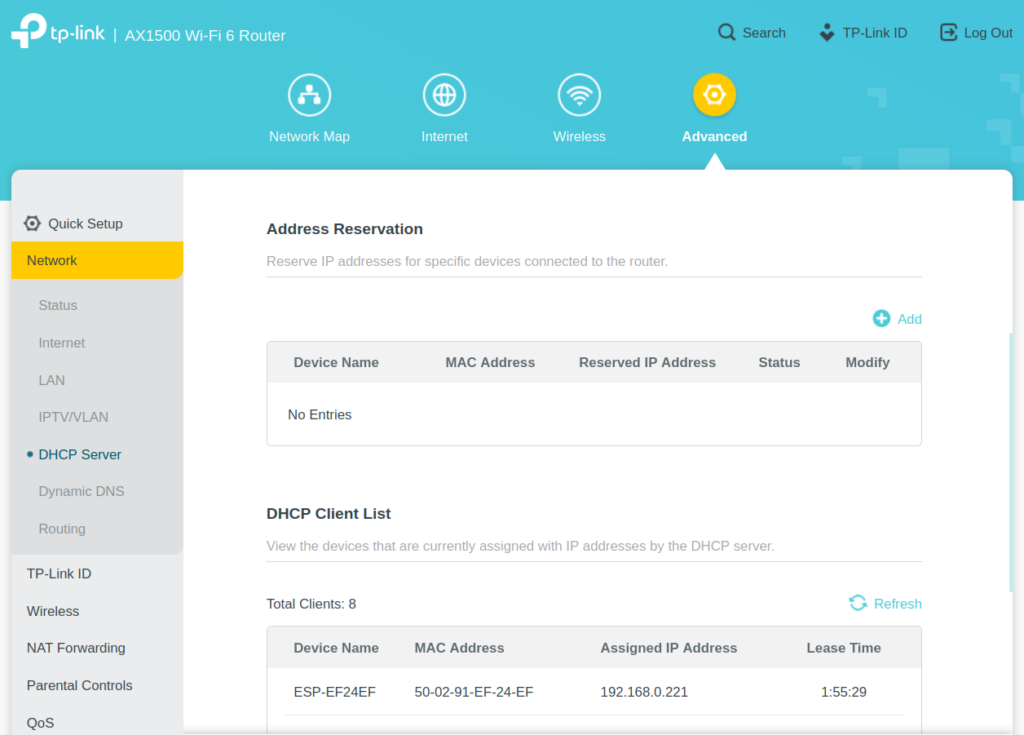
Assign a Static IP
Next we need to set a static IP for the ESP8266 so that your home router does not change its IP address and cause us to lose connection to it. Go to your router’s gateway page or app and find the DHCP settings.
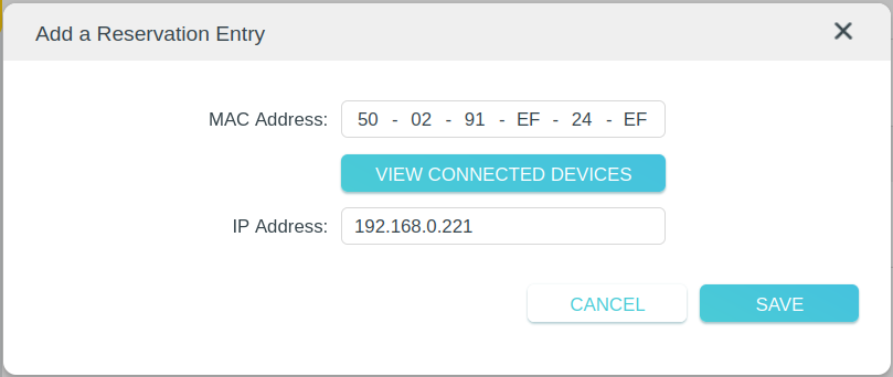
Find the section for reserving addresses and add a new entry using the ESP8266’s IP Address and Mac Address. This will insure that the Router assigns the same IP address to our ESP8266 every time it connects.
Fauxmo
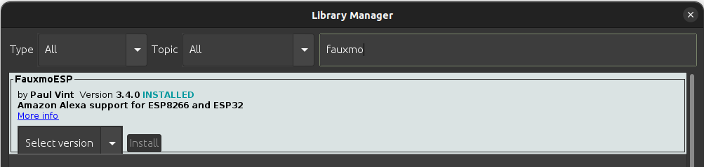
Install the Fauxmo library using the library manager. Fauxmo will allow us to make a device available on Alexa for turning on or off. It emulates a Wemo device and will look like a smart lightbulb on the Alexa side.
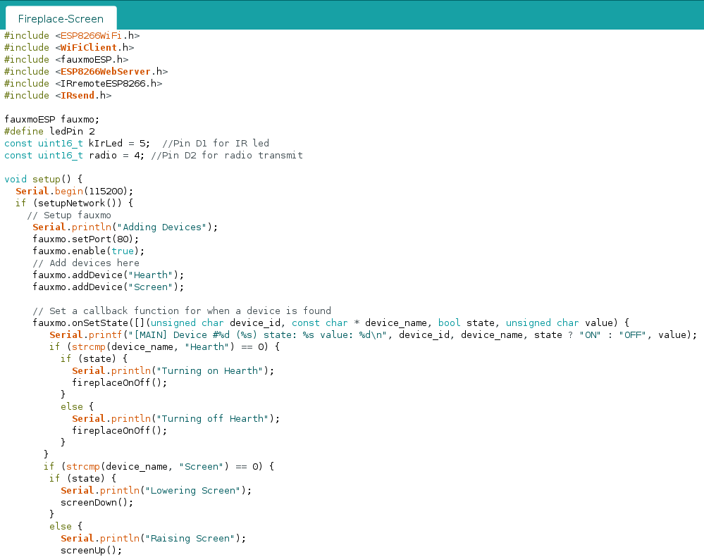
Add #include<fauxmoESP.h> to the top of your arduino file. Declare a variable: fauxmoESP fauxmoESP. Add the following to the setup() function:
void setup() {
  Serial.begin(115200);
  if (setupNetwork()) {
    // Setup fauxmo
     Serial.println("Adding Devices");
     fauxmo.setPort(80);
     fauxmo.enable(true);
     // Add devices here
     fauxmo.addDevice("Hearth");
     fauxmo.addDevice("Screen");

     // Set a callback function for when a device is found
     fauxmo.onSetState([](unsigned char device_id, const char * device_name, bool state, unsigned char value) {
        Serial.printf("[MAIN] Device #%d (%s) state: %s value: %d\n", device_id, device_name, state ? "ON" : "OFF", value);
        if (strcmp(device_name, "Hearth") == 0) {
          if (state) {
            Serial.println("Turning on Hearth");
            fireplaceOnOff();
          }
          else {
            Serial.println("Turning off Hearth");
            fireplaceOnOff();
          }
       }
       if (strcmp(device_name, "Screen") == 0) {
        if (state) {
          Serial.println("Lowering Screen");
          screenDown();
        }
        else {
          Serial.println("Raising Screen");
          screenUp();
        }
       }
     });
  }
}
Make sure to modify the loop() function to have fauxmo.handle(). Also add in your functions for sending IR/RC commands to your devices. Part 1 goes over how to make these commands. These will be used as callback functions for fauxmo to turn on or off our devices. The complete code can be found at this link. Deploy this to your ESP8266 and it will be ready for configuration in the Amazon Alexa app.
Configuring in Alexa
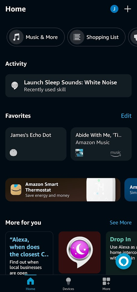
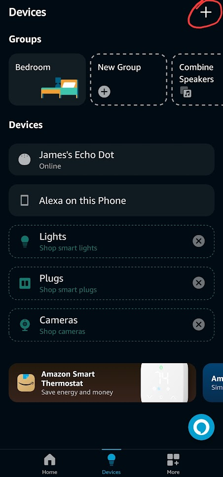
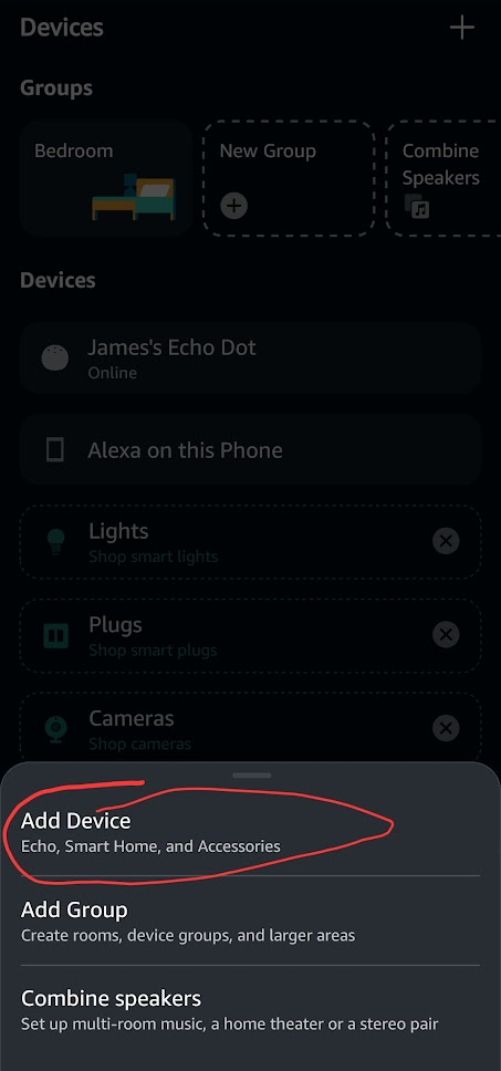
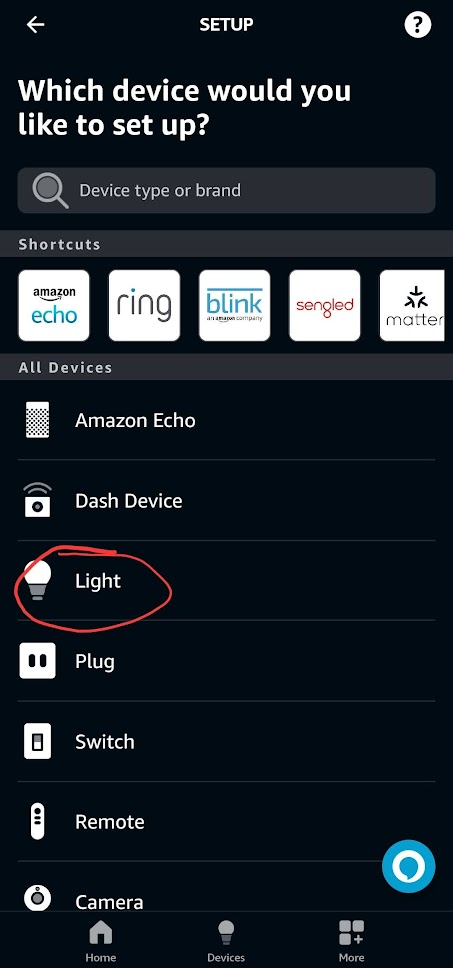
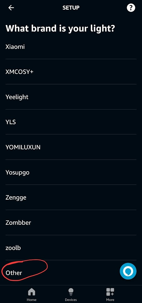
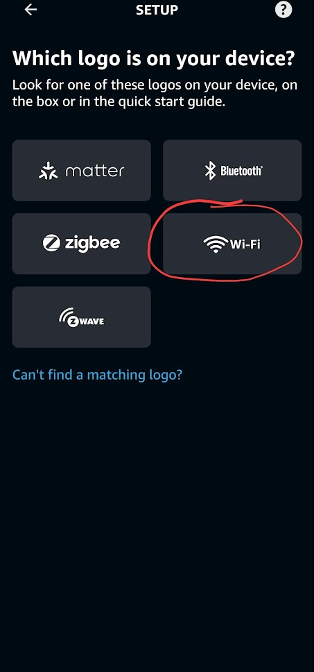
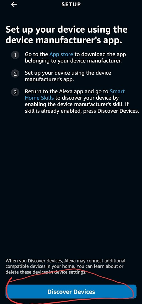
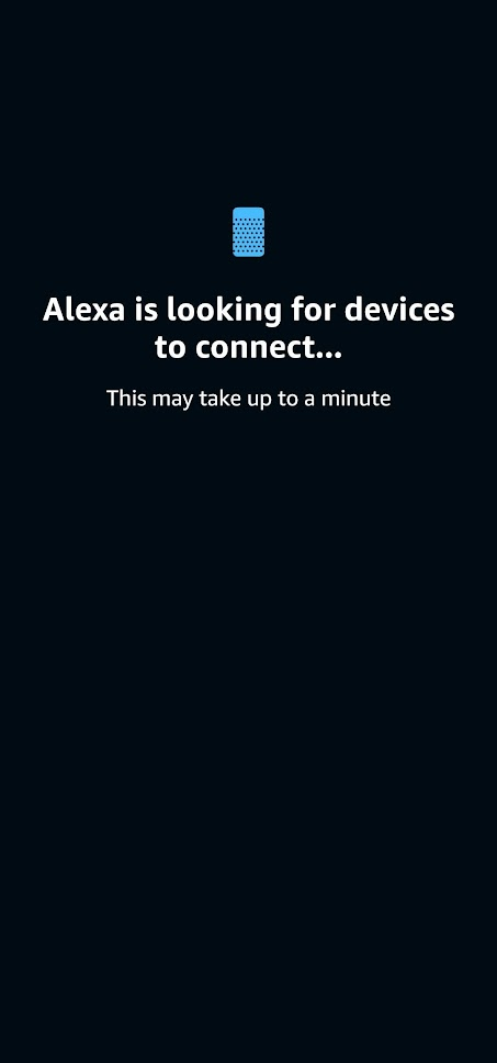
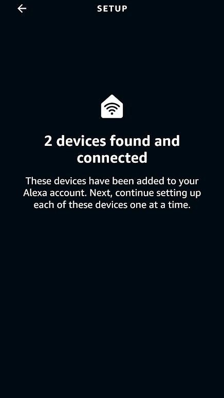
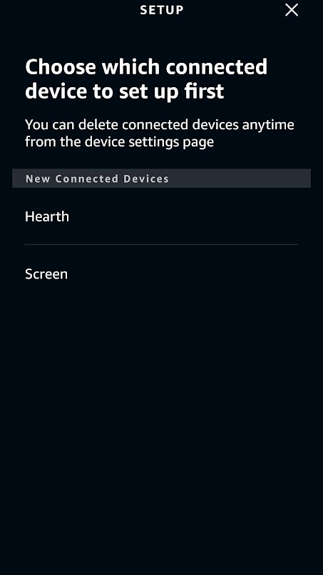
Setting up in Alexa is extremely easy. Once the sketch is deployed to the ESP8266 and the ESP8266 is running fauxmo, it will appear as a smart light when Alexa scans the network for devices. You can ask Alexa to add a device and it will automatically find it or you can follow the screenshots below from the Alexa app.
1
2
3
4
5
6
7
8
9
10
At this point you should be able to ask Alexa to turn on and off your devices successfully. The name of the devices will be the same as the name in the argument to fauxmo.addDevice(“Name”);
Creating a Rest API
The last step in setting up our home media devices is mapping all the different IR/RC commands to endpoints that can be called through network requests.
In the simple example file for sending IR signals, there are three important parts for setting up the Rest API. The first is the routeServer() function in which we will define the endpoints that can be called.
//Server Routing

void routeServer () {
  // Define a default response to the server w/o path
  server.on("/", HTTP_GET, []() {
        server.send(200, F("text/html"),
            F("ESP8266 Controller Basement"));
    });

  // Create endpoints and connect them to corresponding functions
  server.on("/rcDeviceOn", HTTP_GET, RCDeviceOn);
  server.on("/rcDeviceOff", HTTP_GET, RCDeviceOff);
  server.on("/rcDeviceStop", HTTP_GET, RCDeviceStop);

// If endpoint called that doesn't exist, call handleNotFound()
  server.onNotFound(handleNotFound);
}
Each server.on(“/path”, Method, Function) defines an endpoint that can be called with an https request to serveraddress:port/path.
The next important function is setupNetwork() where we previously set up the wifi connection. We need to add a call to routeServer(), enable CORS, and start the server.
boolean setupNetwork() {
// Let us connect to WiFi
WiFi.mode(WIFI_STA);
String ssid = "<Wifi-Network-Name>";
String password = "<Wifi-Network-Password>";
WiFi.begin(ssid, password);
while (WiFi.status() != WL_CONNECTED) {
delay(500);
Serial.print(".");
}
Serial.println(".......");
Serial.println("WiFi Connected....IP Address:");
Serial.println(WiFi.localIP());
Serial.println(WiFi.macAddress());
// call therouteServer()
routeServer();
// enable CORS
server.enableCORS(true);
// start the server
server.begin();
Serial.println("HTTP server live");
return true;
}
The third function is handleNotFound() which is called when an endpoint that doesn’t exist receives a request. It simply sends back to the requesting client a 404: Not Found error.
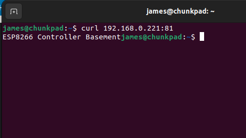
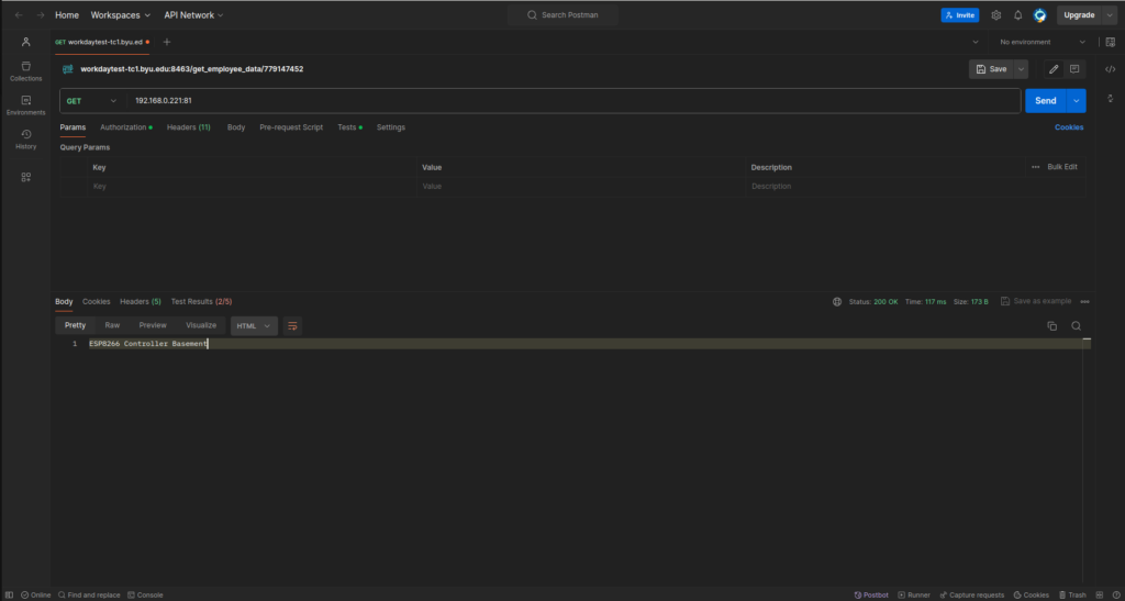
Deploy to the ESP8266 and you should now be able to send requests to your server. If your ip address was 192.168.0.221 and you set the port to 81, you should be able to use the terminal or software like Postman to test your server’s endpoints.
TerminalPostman
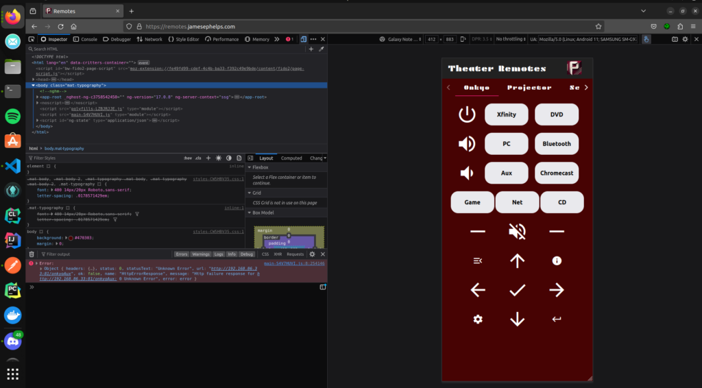
Calling from a Webapp
For my use case, I created an angular app that basically consisted of buttons like a remote. When clicked they would call the endpoints on the ESP8266, thus sending the corresponding IR/RC signals to control whatever media device. The webapp runs on an old laptop connected to the home network. The interface of the webapp can be viewed at remotes.jamesephelps.com.
Each button calls a function like this one below to send requests to the ESP8266
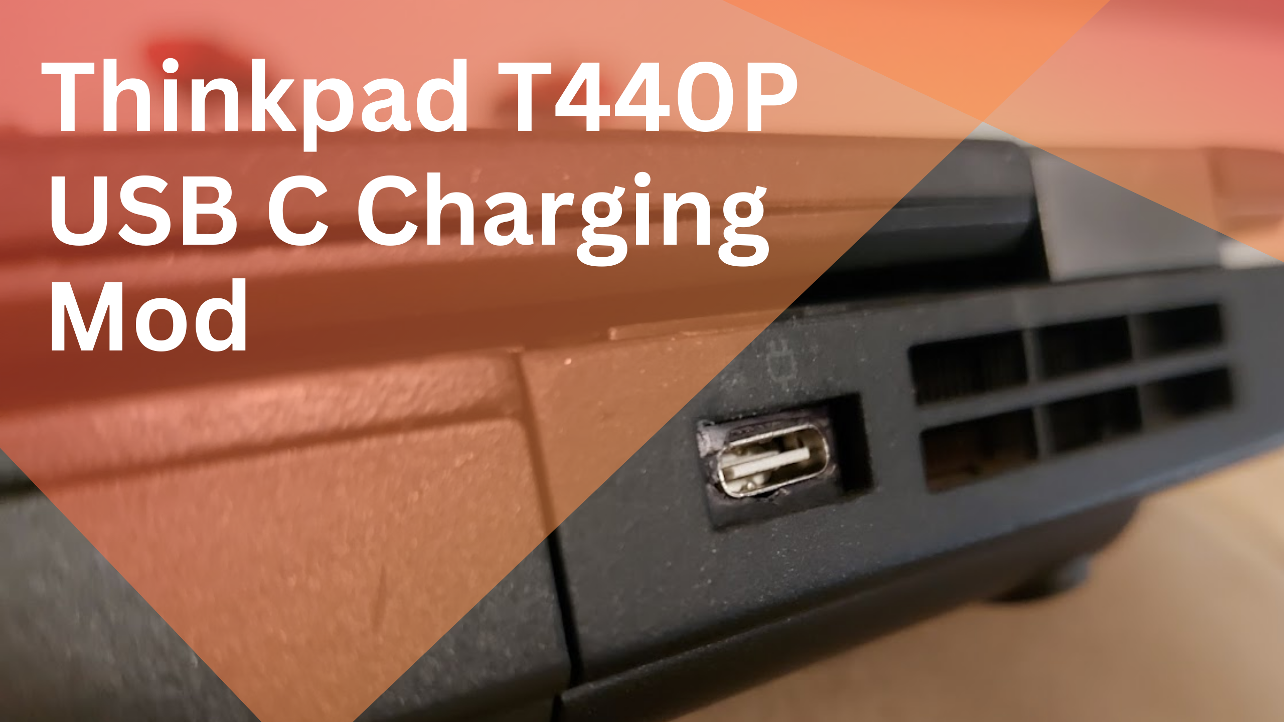
The Thinkpad T440P comes with the old Lenovo Slim USB charging port. In my experience, it has only been a source of annoyance as it seems every charger for it stops working after about six months. In this article, I will go through the process of converting the laptop to a USB C charging port. This is a decently well documented mod and is not very difficult to do with a little soldering.
The items required for this mod are a USB C PD trigger module, a soldering iron, a multimeter, and an approximately 500 Ohm resistor. The USB C PD trigger module just needs to provide 20V. This is the module that I happened to use:
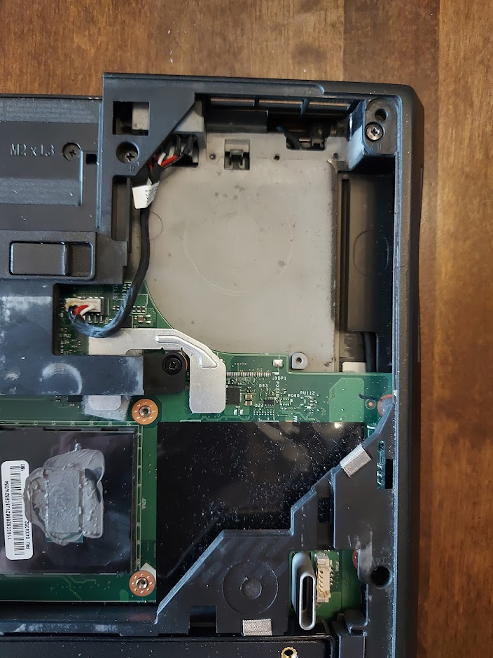
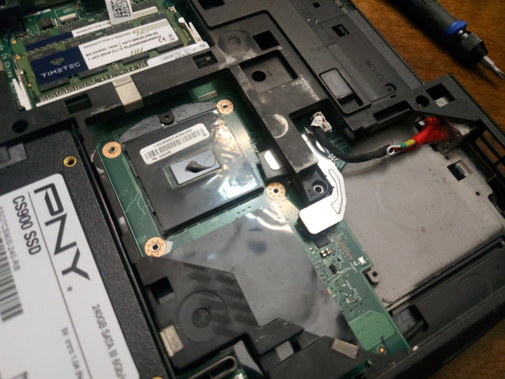
The first step is to remove the old Slim USB charging port. This requires removing the fan from off of the CPU to get access to the port.
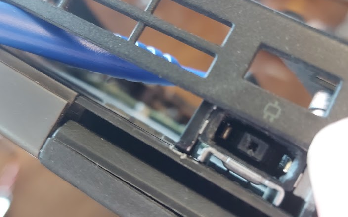
Since we have exposed the CPU and messed up the thermal paste, that will need to be reapplied later before the fan is put back on. There are tabs holding the old port into the encasing. Using a thin screwdriver to open up space between the old part and its holdings is the best way to wiggle it out. For me this was pretty difficult to do and involved a lot of gentling, yet violently smashing of the old port so that it would come out.
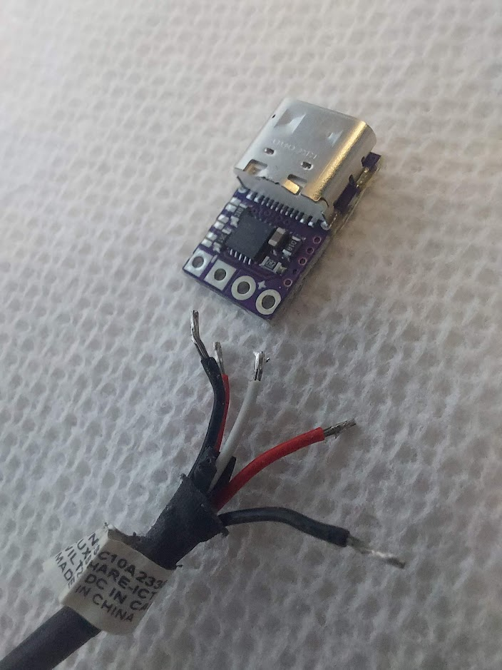
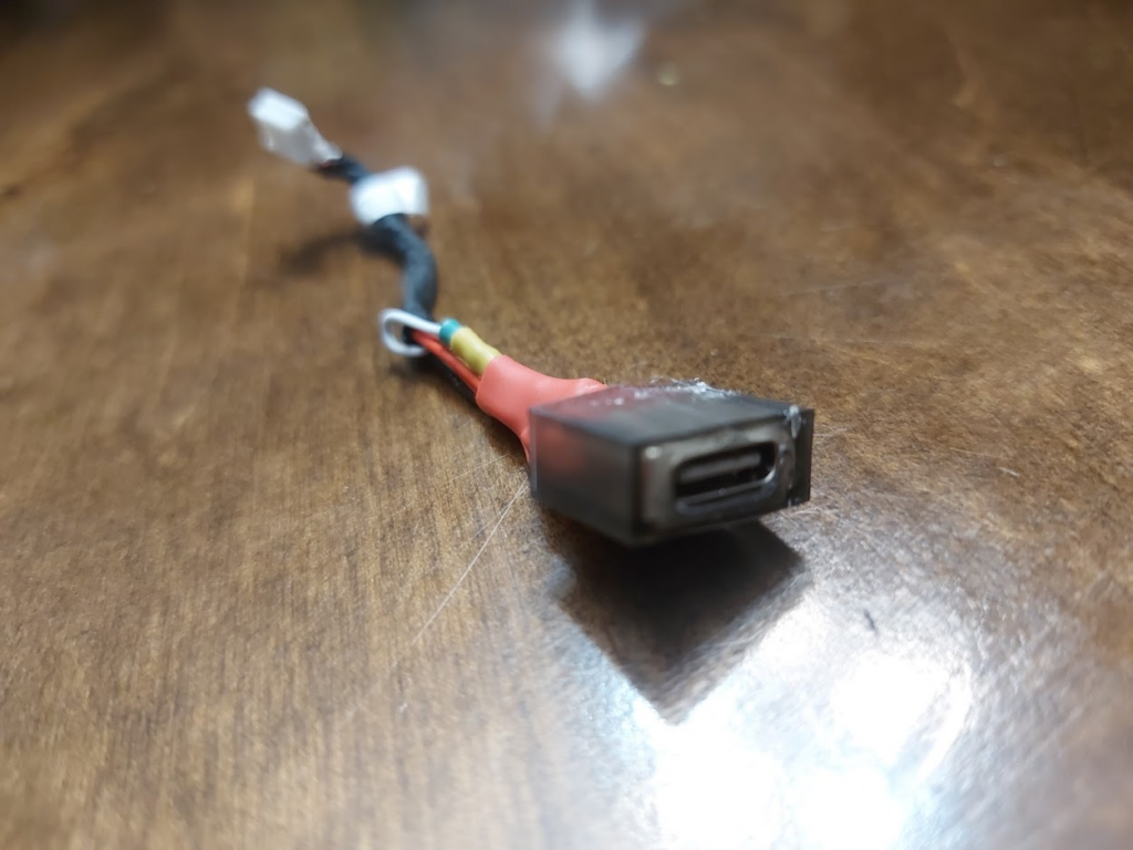
Once the old port is removed, we can salvage the cable from it to build the new USB C port.
The USB C Port
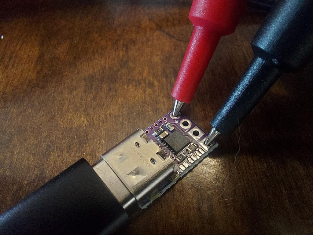
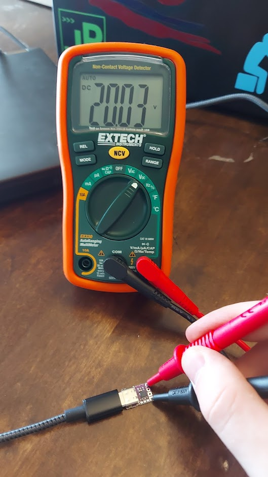
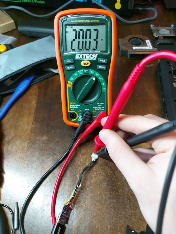
We can use a multimeter to test the output voltage of the USB C PD trigger module to insure that it is 20V.
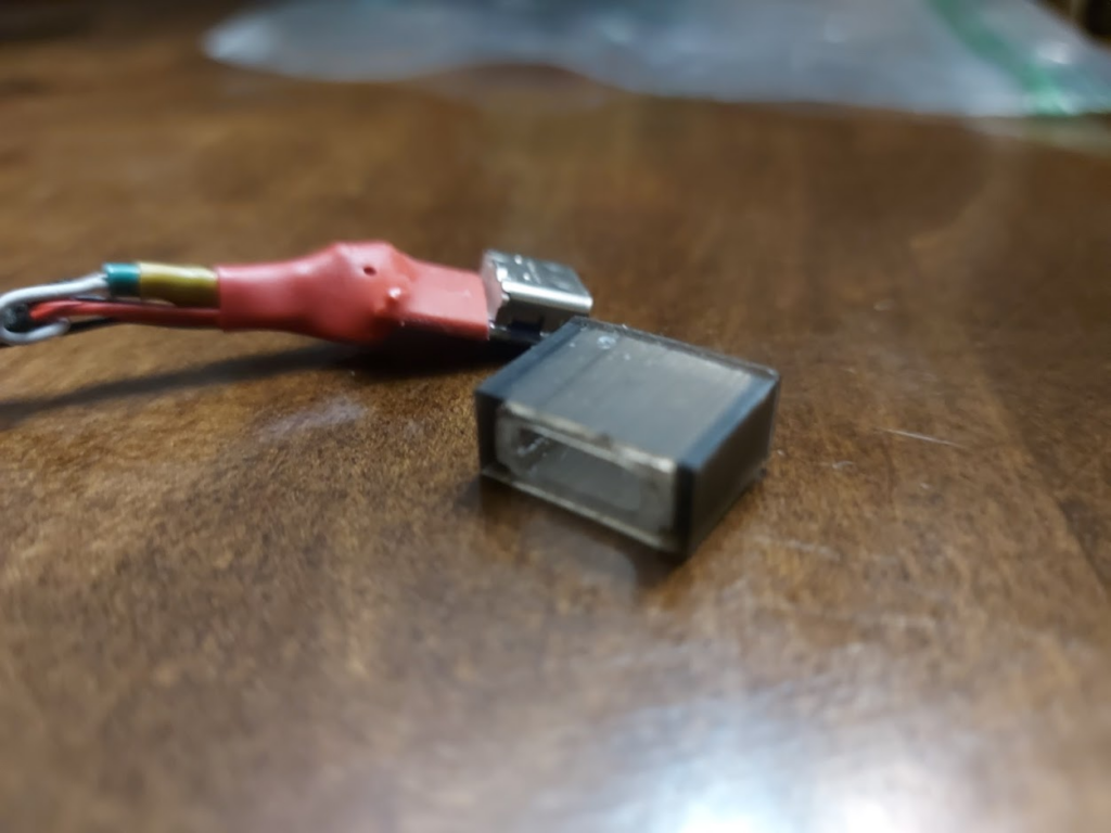
Once I was sure that the USB C Trigger module had the correct output, I desoldered the Slim USB port from its cables and separated them out.
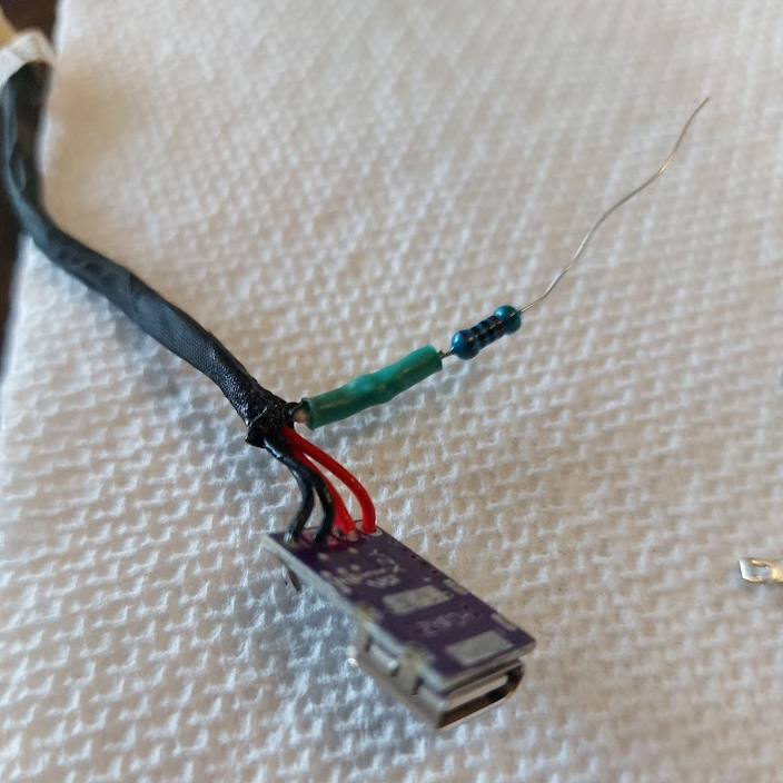
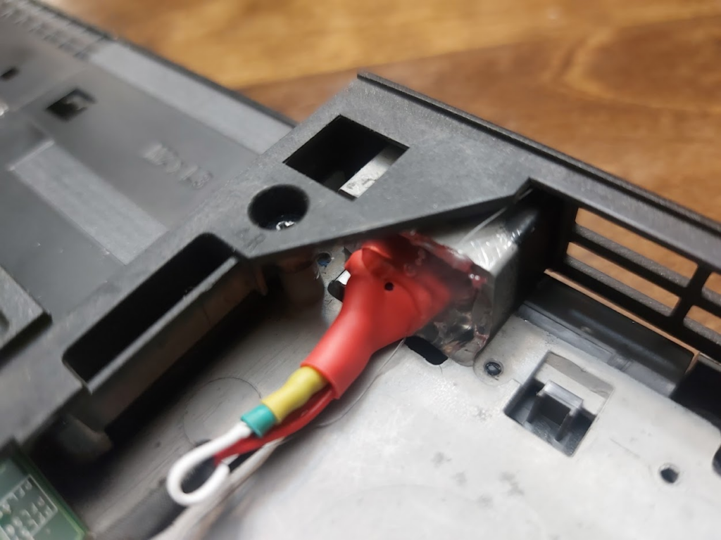
Next, I soldered the black cables to the negative side and the red cables to the positive side. The white cable is a sense wire for detecting the wattage for the computer. It needs to have a resistor attached and then it can be soldered to the negative side with the black cables. The resistor should be around 500 Ohm, it doesn’t need to be exact to work correctly.
Finally, I double checked to make sure that on the end that goes into the motherboard, we were still getting 20V.
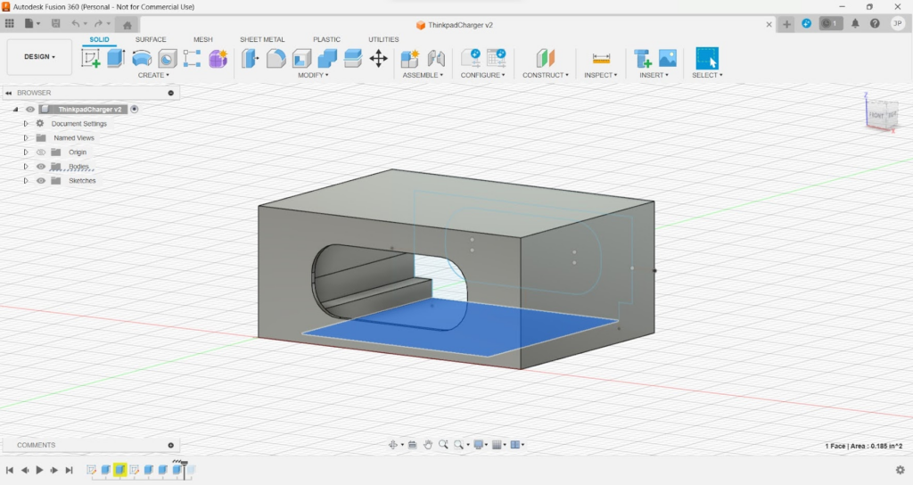
A New Port Housing
Using a dial caliper, I measured out the dimensions of the hole for the port and the module and designed a new port housing using Fusion 360. If you dual boot like me, make sure to have your time set correctly in your OS for Fusion 360 or it will never load and never tell you why.
It was during the holidays when I did this, so all of the libraries and universities around me with 3D printers were closed. I opted to use a 3D printing service online which ended up taking over a month to print and then ship my part to me.
I put the port inside the housing using hot glue. The hot glue worked okay, but I would have preferred something a little bit stronger.
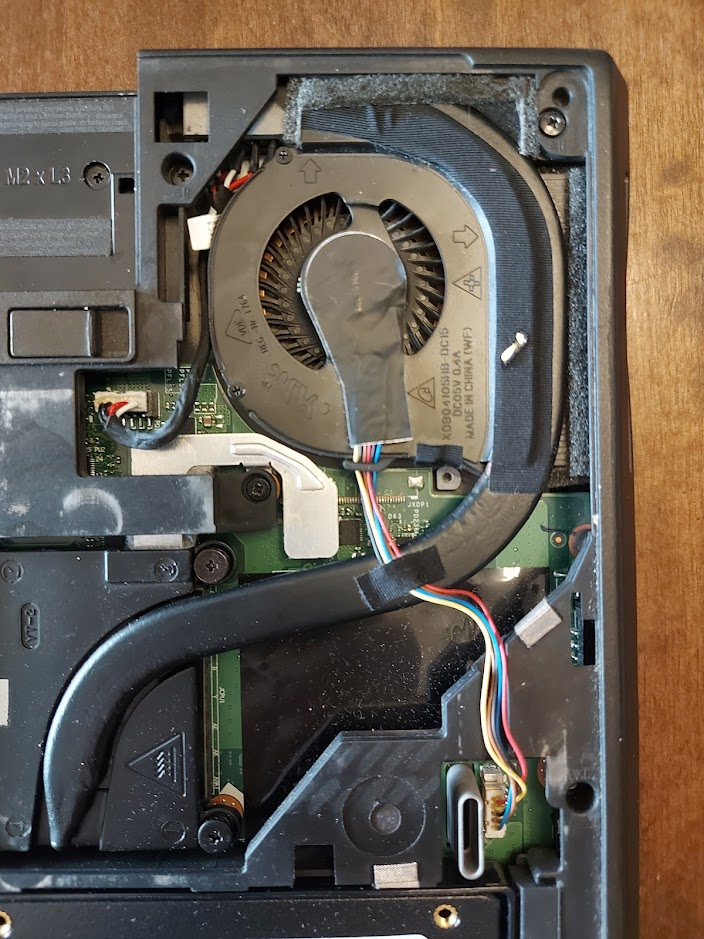
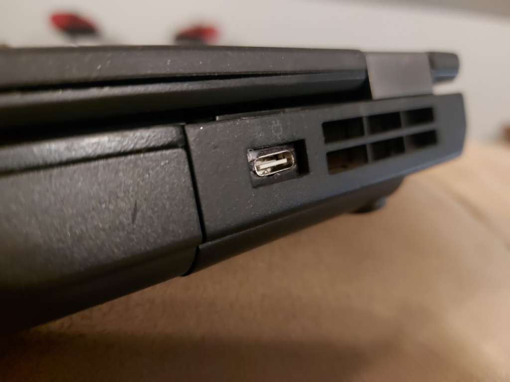
Putting it all together
I slid the port into the laptop and then filled up the back with hot glue to hold it in. Again, the hot glue doesn’t feel super sturdy, but it has held it in so far.
Lastly, I cleaned up and reapplied the thermal paste before putting the fan back onto the CPU.
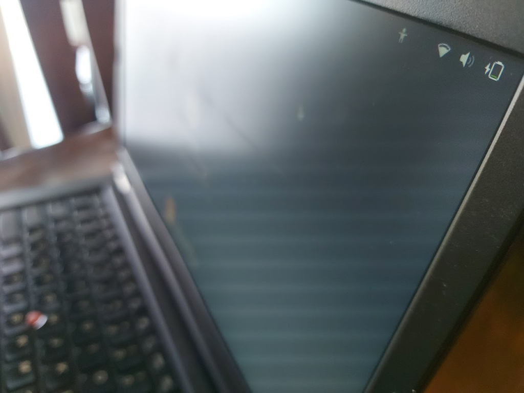
In the end it worked and the port does not look terrible. It was a little bit of a squeeze to move the cable over so the fan could go back in. Might be a good idea to make sure the back of the port is not too rigid. If I could do it again, I would probably find an alternative solution to hot glue for holding it in. In theory, this is supposed to go with a 90W charger, but if the laptop is off it will slowly charge alright with a lower wattage.
In this series of articles I will be going over my efforts to create a home media control system using a couple ESP8266’s. The end result will be a fully automated theater setup through Amazon Alexa and a webapp built in Angular. This series will go over setting up an ESP8266 to read and transmit both IR signal and RF signals, making controllable smart devices for Alexa, creating a locally hosted webapp for remote control, and the steps to properly configure a home network.
The following video shows the end result using Alexa to turn on all devices in the home theater. This setup includes a video streaming box, surround system, projector, radio-controlled projector screen, and an electric fireplace. The specific device information is listed under the video.
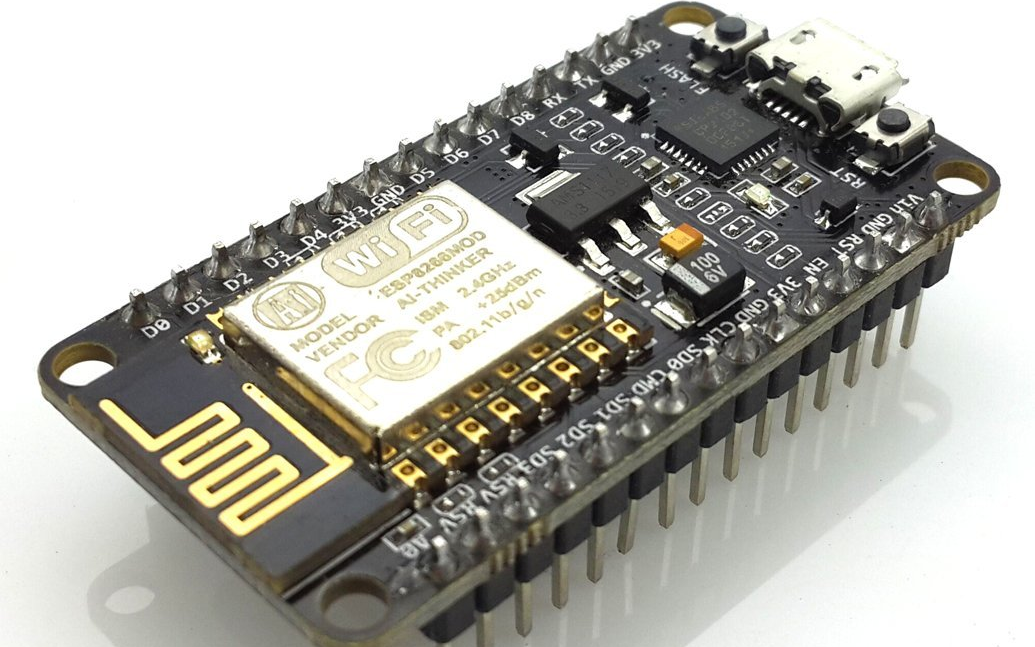
For this project, I will be using Nodemcu ESP8266 Development Boards that I purchased off of Amazon. These can be found for cheaper from websites that ship from China, but I was on a time limit since I will be returning back to school soon, so I went the faster Amazon route. I specifically used the HiLetGo models which seemed to work. Of the three I bought, one arrived dead, but the other two were fine.
The ESP8266 is a microcontroller that can be easily programmed through a micro usb connection using an IDE like Arduino. The ESP8266 is special because it has wifi capabilities and a very strong community behind it, making resources for it readily available on the internet.
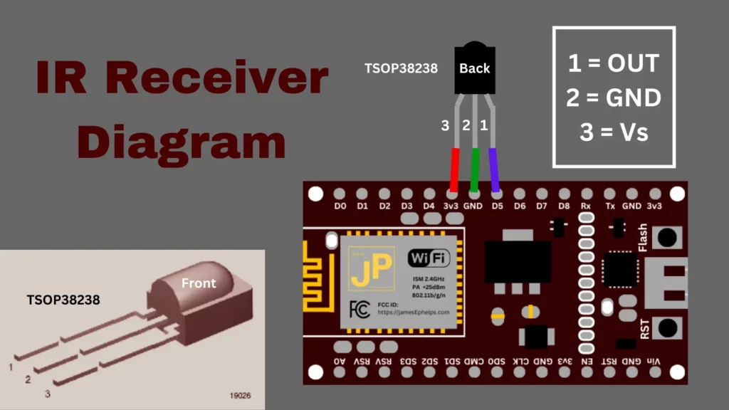
In addition to the boards, I also purchased an IR Receiver and LED from Adafruit. These will allow us to read Infrared signals from the remotes and then be able to replicate them ourselves on our ESP8266 to emit the same signals as our remotes. I also got a tiny breadboard from Adafruit to allow for easier prototyping before I permanently soldered components to the ESP8266’s.
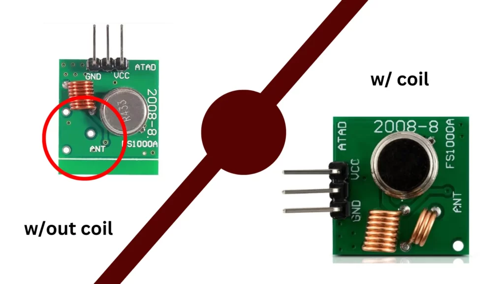
Lastly, I also ended up needing to get a 433 MHz RF receiver and transmitter for the projector screen. The projector screen is controlled by an RF remote which emits radio signals. When searching for such a receiver and transmitter, I found many transmitters that seemed to be missing a coil on Amazon as shown below.
What effect this has is outside of the scope of my knowledge, but several reviewers indicated the coil is necessary for proper functioning, so I was sure to buy one with the coil. For me, all the product listings when I first searched on Amazon were missing this coil. I had to search for a while before I found one that seemed to actually have the coil.
Receiving IR Signals
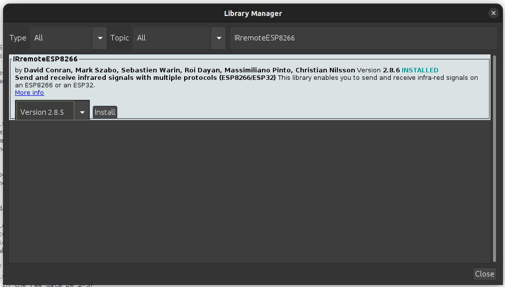
Most devices are controlled using IR remotes which emit an IR signal that the device can pick up on using a receiver. To get our needed signals, we will connect the IR receiver to our ESP8266 board and then record data that it picks up from our remotes. We will use a library called IRremoteESP8266 that can be found in the Arduino libraries to understand the data that the receiver picks up.
In Arduino, go to Tools>Manage Libraries… (Ctrl+shift+I). Search for “IRremoteESP8266” and install the only one that pops up.
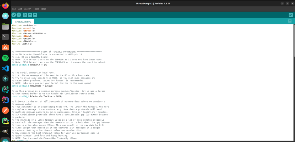
Now go to your file manager and find where Arduino is installed. From there go to libraries/IRremoteESP8266/examples/IRrecDumpv2 and open in Arduino the IRrecDumpv2.ino file.
This sketch allows us to receive codes from the remotes on the ESP8266. The top section has a couple of parameters you can edit to fine tune your setup. It is likely you will not need to modify this at all. For mine to work, I had to change kMinUnknownSize to a very high number, because I was picking up random numbers on my receiver.
Deploy this sketch to your ESP8266 by pressing the arrow up in the top left. This will pop up a terminal, displaying the status of the compiling process and then the write process. Now we need to actually connect the IR receiver to our ESP8266.
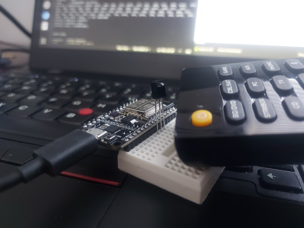
I was able to use the breadboard and just plug the receiver in since this is a super simple setup. Once the receiver is connected, keep the board connected to the computer, and open the serial monitor in Arduino.
I had to put the remote pretty close to my receiver for it to pick it up for some reason
If successful, each time you press a button, output should show up in the serial monitor that looks like this:
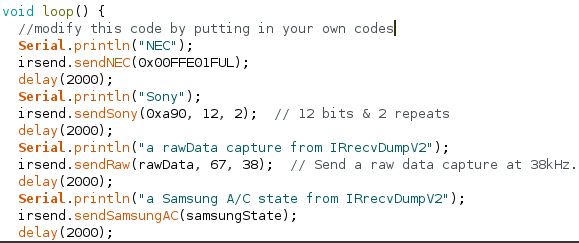
Go through each button on the remote that you want and record what it outputs to the serial monitor. We will use the code (ex. 0x10EF8877), the protocol (ex. NEC), and the amount of bits (ex. 32 Bits) when we send a signal to the remote. Later when we write the code to send the signals it will be done similar to this this:
I keep getting code 0xFFFFFF in the serial monitor
In the NEC protocol, 0xFFFFFF is the repeat command and simply means that whatever the last command sent by the remote is needs to be repeated. Just ignore these and keep sending signals with the remote until you get a code that is not 0xFFFFFF
I am only getting question marks in the serial monitor
Make sure that your baudrate in the serial monitor is set to the same as was set in the above sketch (probably 115200). If the baudrate does not match, you might just get a bunch of question marks in the serial monitor.
I am just getting continuous random output in the serial monitor
Check to make sure that the wiring is correct. If it is and the problem persists, try setting the kMinUnknownSize variable in the sketch to 10000 and re-deploy the sketch to your esp8266.
Sending IR Signals
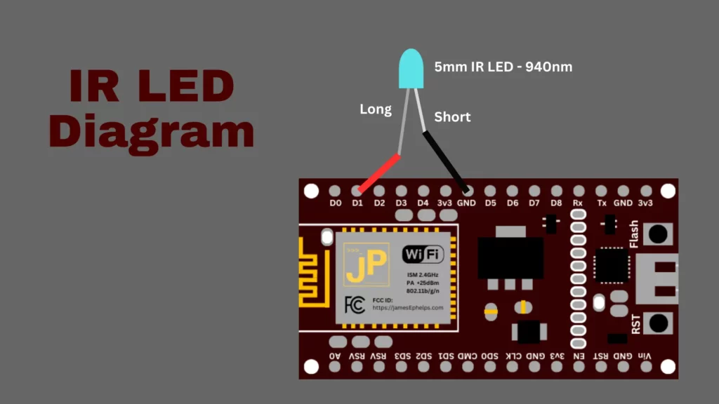
To send the signals that we recorded, we must first wire the IR Led up to our ESP8266. The following diagram shows the proper way to connect the Led to the board.
This should be pretty easy using a breadboard and some wires. To test if your remote signals work, navigate back to your Arduino folder like previously and go through the folders: libraries/IRremoteESP8266/examples/IRsendDemo and open the IRsendDemo.ino file. If you followed the diagram above, you will need to change kIrLed variable to 5. Now, put your own codes in the loop() so that your ESP8266 will continuously send your signals so we can test them. Deploy this new sketch to your board.
If you want to check if your board is sending any IR signals at all, you can look at the IR led through your phone’s camera. If it is working, you will see distinct purple flashes. If you have the correct codes, it will now be able to interact with your controllable devices just like your original remote does.
Receiving RF signals
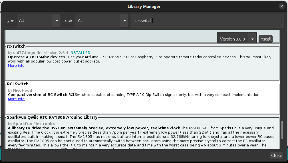
If you have a device that is radio controlled by 433MHz, we can use the rc-switch library to decode and transmit radio signals. Go back to the library manager (Ctrl+shift+I) in Arduino and search for rc-switch to install. Make sure to install the one by sui77 and fingolfin.
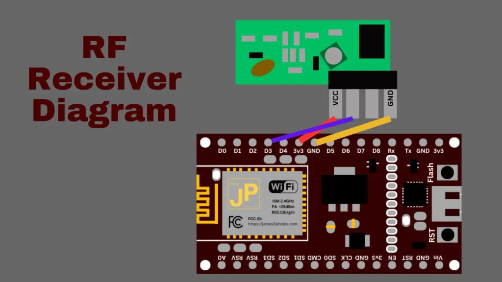
Next, go to the Arduino folder and navigate through the following folders libraries/rc-switch/examples/ReceiveDemo_Simple/ and open ReceiveDemo_Simple.ino. This sketch allows us to use the RF receiver to get codes that represent the radio signals from our RF remotes. Deploy this sketch to the board. (You may need to adjust the baudrate if you are using a different rate. This is done in the code at Serial.begin(9600) where 9600 is the baudrate) Now, wire up the receiver as shown in this diagram.
If done correctly, you should now be able to press buttons on your RF remote and data will show up in the Serial Monitor. There are three things we’re are looking for: a code, a number of bits, and a protocol number.
6582737
24bit
Protocol: 1
Transmitting RF Signals
To test if the RF signals we picked up work, we can use the provided SendDemo.ino file in the folders Arduino/libraries/rc-switch/examples/SendDemo/. If you got the output from the previous example, you would test it by adding a line of code to the loop() function like so:
The wiring for the transmitter is done as follows:
If you are using this same setup, you will need to change the line in the sketch mySwitch.enableTransmit(4); so that it uses pin 4 which is D2. Deploy the sketch and you should now be able to control your RF device using the ESP8266.
In summary, following these steps, you should be able to get all the data from your remotes and devices that you will need in order to control them. In part 2, we will go over actually doing the programming so that voice assistants like Alexa or a custom webapp can send these signals to the devices.
Last year I was able to snatch a refurbished Thinkpad l15 Gen 2 from Lenovo for $200. Recently I noticed that the USB port on the right didn’t actually work. Upon further inspection I found the pins inside were sunken. After some attempts with tweezers to reposition them so they would come into contact with USB devices, I succeeded in mangling them even worse, insuring they would never work again.
Fortunately, the damaged USB port was the on the right which is part of a USB and 3.5mm audio board, separate from the motherboard. Had it been on the other side, it would have required a motherboard replacement to get a working USB port again. After watching on Ebay for a good price, I was able to find a replacement USB Audio board for $8. For reference, the part number is 5C50S73039.
Installation
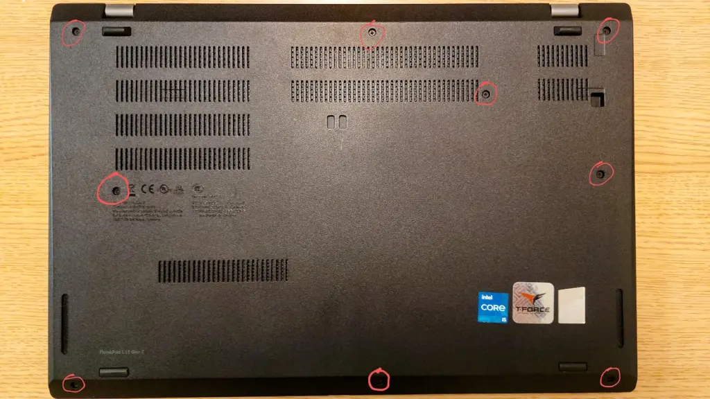
First, remove the bottom panel. There are 9 screws that need to be loosened. They will not come out completely, because the bottom panel holds onto them so they don’t get lost.
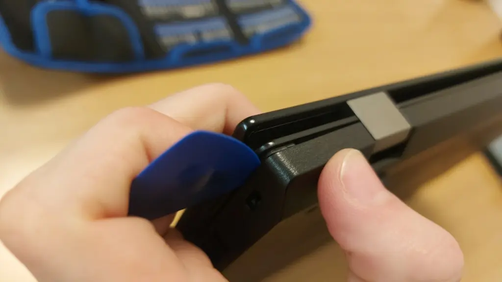
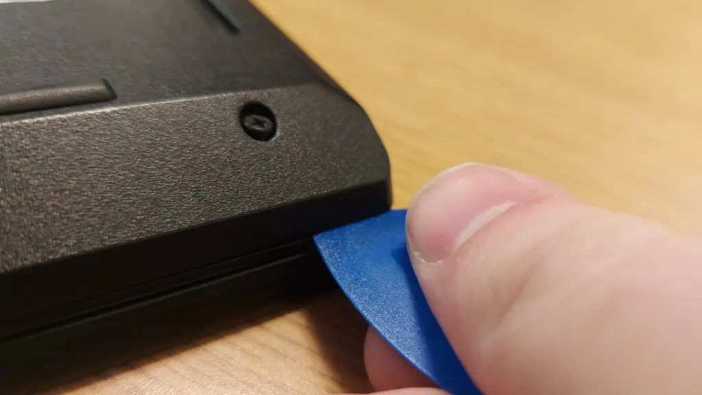
Once the screws are loosened, we need to pry open the hooks holding it onto the laptop. Insert a small, non-metal edge (a credit card could work) into the seam between the panel and laptop. Go around the entire perimeter of the laptop, gently popping it open. You should feel and hear a pop as each hook is undone. Make sure there is no micro sd card in the slot or you won’t be able to pry the panel off.
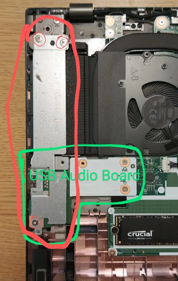
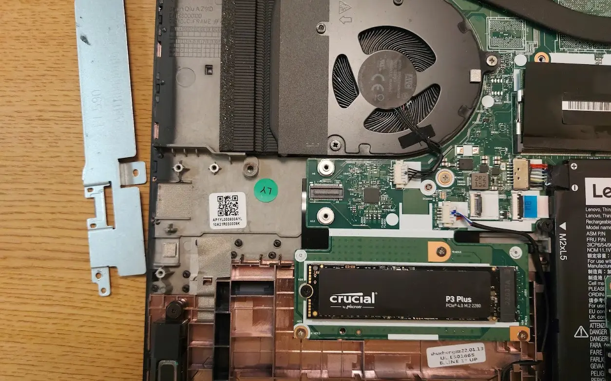
Once the panel is off, we need to remove the metal cover on the side. This is covering the USB Audio board. Mine had three screws holding it in. After removing the screws, the metal panel should come right off, revealing the USB Audio board.
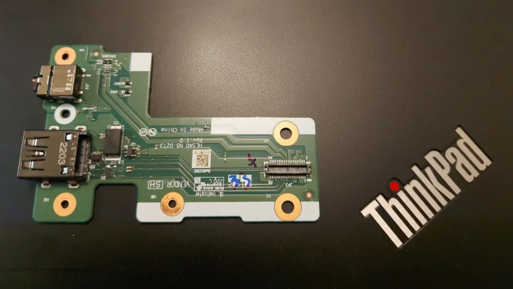
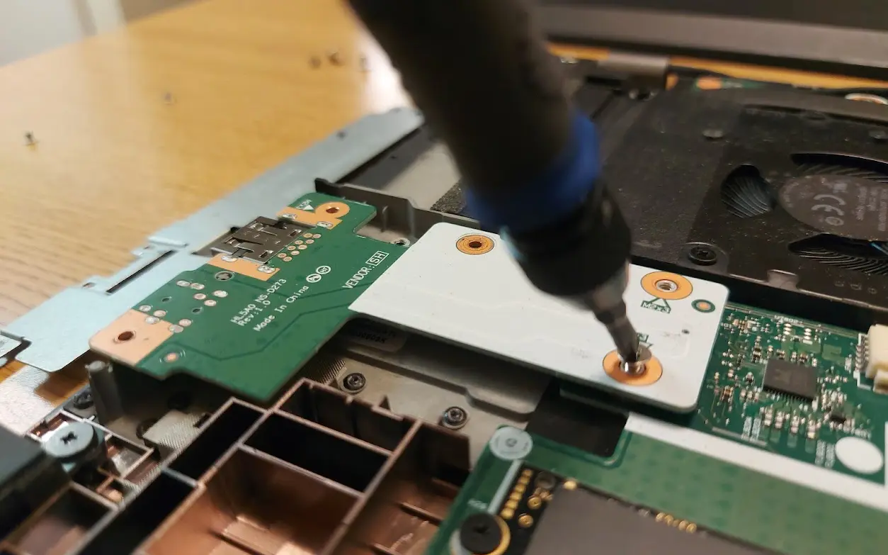
Remove the screws from the USB Audio Board (mine had only three screws again). Then you should be able to gently lift it straight up. It is plugged into the motherboard on the underside, so there will be a little bit of resistance.
Removing the ScrewsThe Laptop with the USB Audio Board Removed
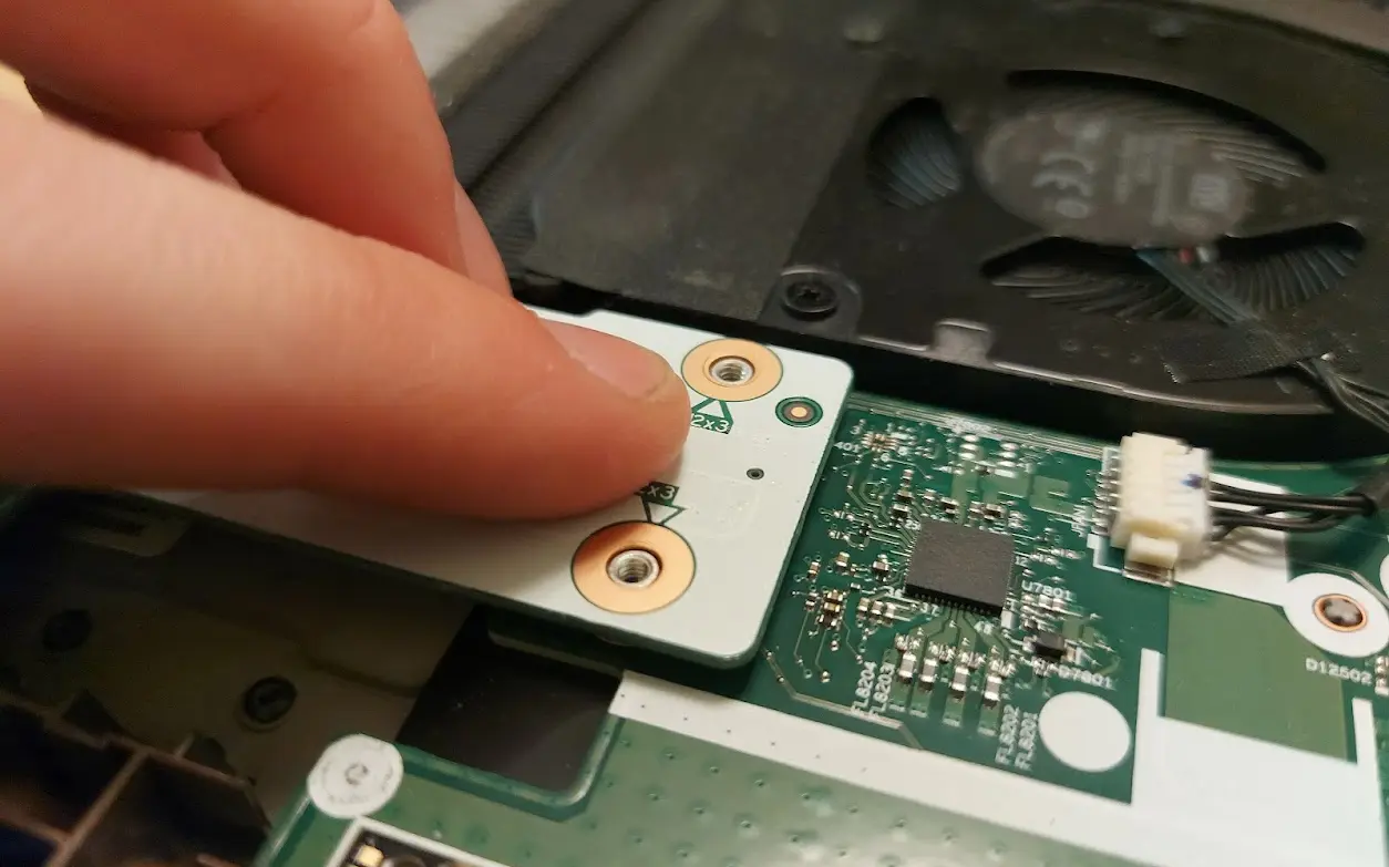
Put the new board into the laptop, using the screw holes as guides to position it correctly. Push the end firmly down to plug it into the motherboard.
Pushing the Side to Plug it in
Screw the USB Audio Board back in, then the metal plate, and then finally gently press the bottom panel back onto the laptop and re-tighten all of the screws. If done correctly, the new USB and 3.5 mm ports should be fully operational.
Now the first thing you want to do, is find a GoPro stand not out in the open. Take a thin strip of metal and stick it into the crack between the glass and…
Research
GoPro cameras are pretty nice, but they are also pretty expensive. Even buying older, refurbished models will still set you back a couple hundred dollars. This is the story of how I obtained one significantly cheaper than normal. (And also how to fix broken protective glass on the Hero 8)
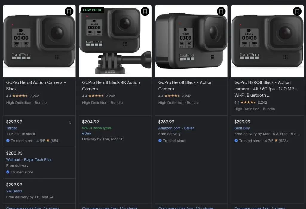
My target in this endeavor was the GoPro Hero 8 for a couple of specific reasons which I will cover. At the time of this writing, buying a Hero 8 is still over $200. In the end I ended up paying about $110 for one.
The GoPro Hero 8 stands out from the other GoPro Hero models because it does not have a removable protective cover for the lens. This is normally considered the major downside of the Hero 8. Once it is cracked, most consider it a paperweight. GoPro themselves will not do repairs on Hero 8’s with cracked protective glass. Fortunately, this fact proved beneficial to me because is it is actually very easy to repair and relatively cheap.
While, GoPro does not sell protective glass covers for the lens, Camera Butter, a company in British Columbia, manufactures such a glass cover. From appearances and my limited research, it appears to be on par with the original protective cover. It is made of Corning Gorilla glass and the company owner claims in this Reddit post, that the adhesive is the same as the original.
Having identified the method of repair, I started to search the internet to find a “broken” GoPro Hero 8. Luckily, I was able to find one from a camera rental company fairly quickly. The description noted that its protective lens cover was completely shattered, ruining the functionality of the camera. I ended up purchasing this one despite it being more pricy, because it had a 30-day return period and the company was a lot more reliable than Ebay sellers.
The total cost including shipping was about $110, but I was able to find a good promo code online that knocked it down to about $90. The camera came in its original packaging and included the normal accessories and charging cable. The camera plus the lens brought the total cost up to just under $110.
Repair
The first thing to do was remove the old broken glass and adhesive residue from the camera. This camera was so badly damaged, that the protective glass was already pretty broken off, so I could remove it easily.
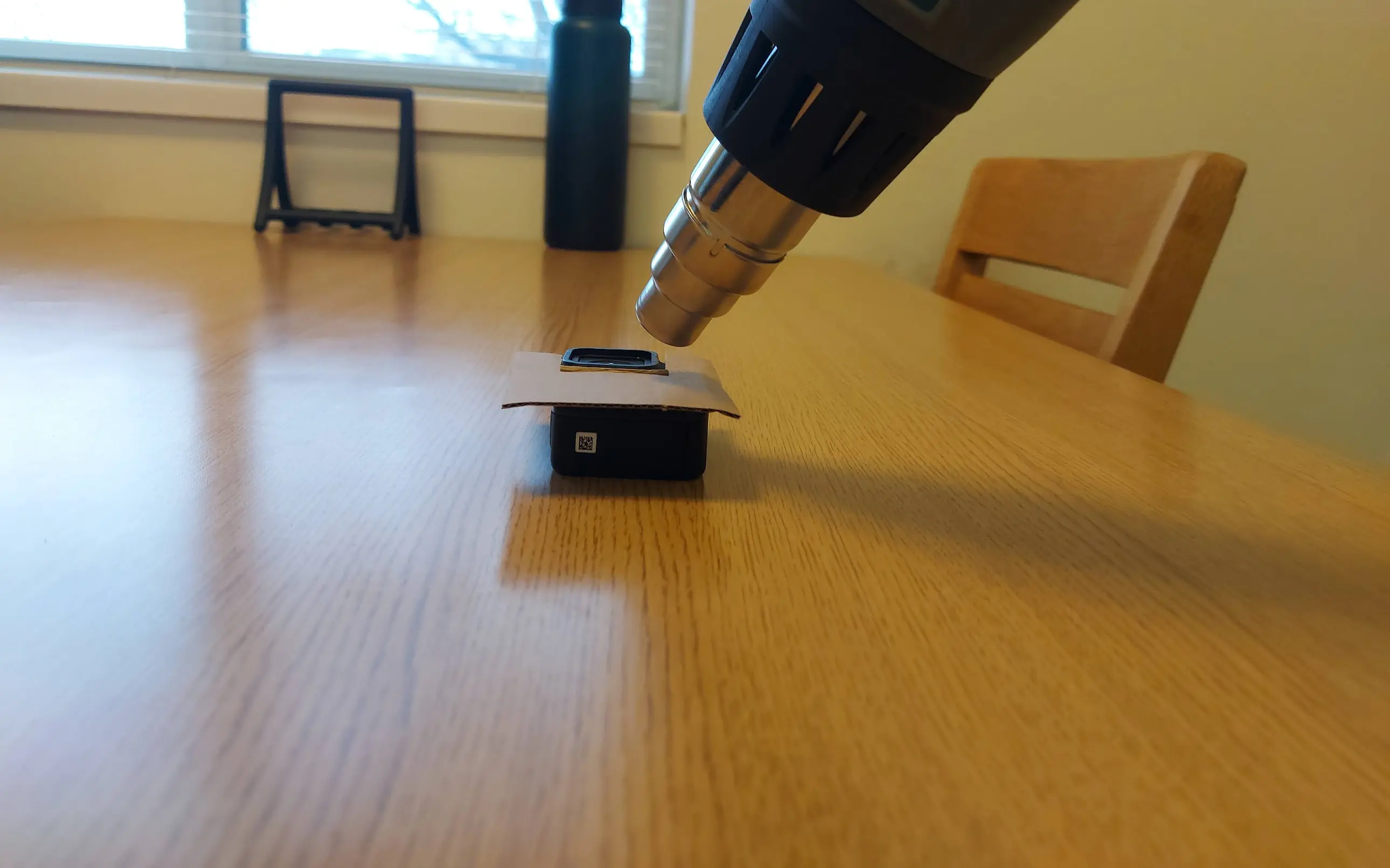
If the damaged lens cover is still fairly intact you can get it to come off by heating the adhesive up using a heat gun or hair dryer. Camera Butter has an instructional video and it is also demonstrated in this youtube video. You just have to heat it up for about a minute and a half and it will loosen up enough to let you pry it off.
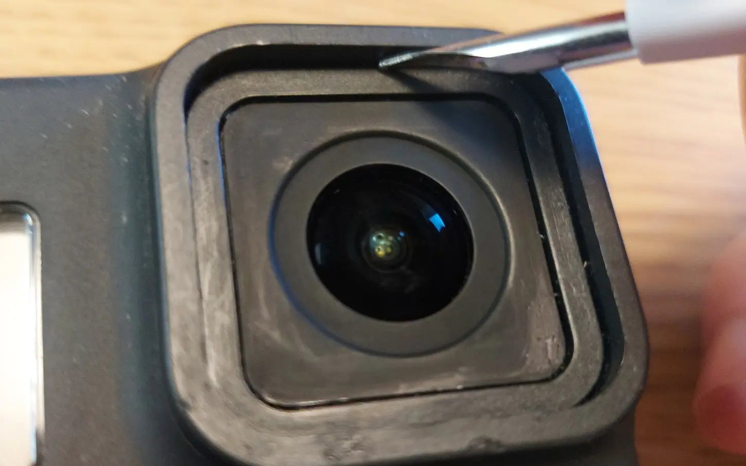
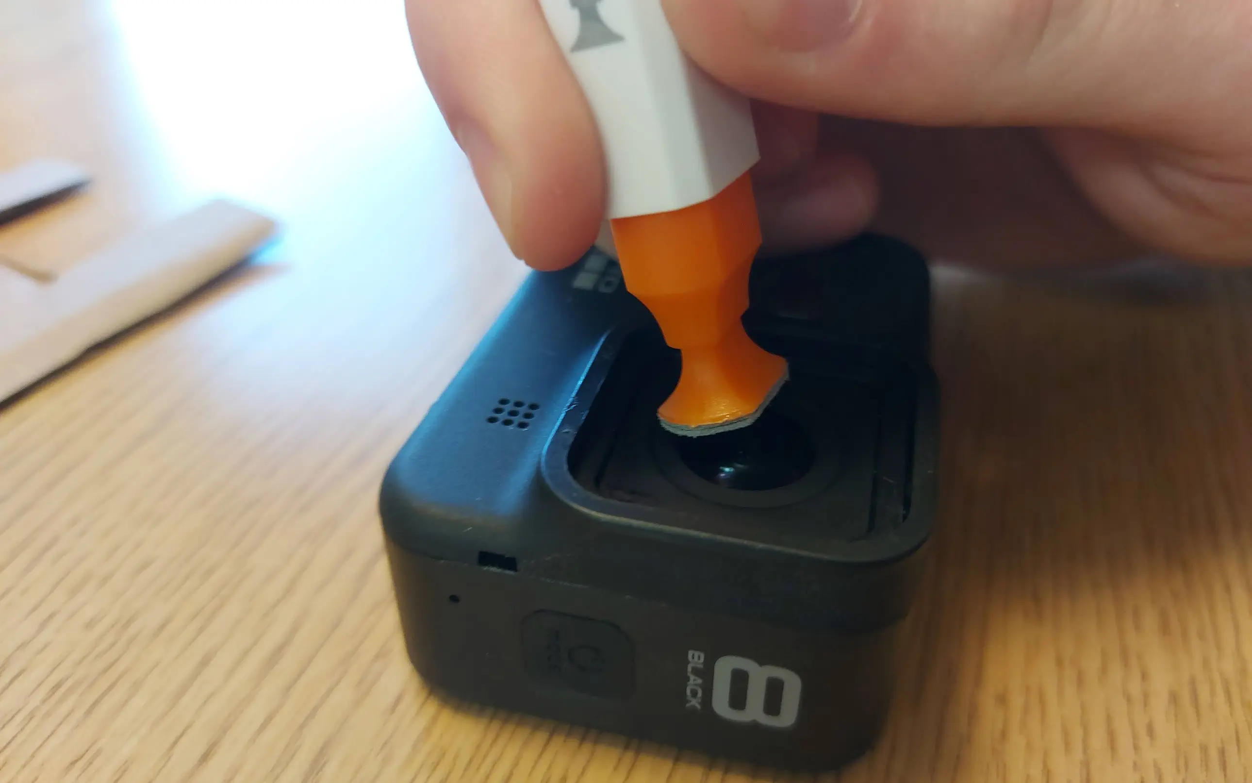
I removed the residue using a metal pen-like tip to scrape it off of the edges of the lens compartment.
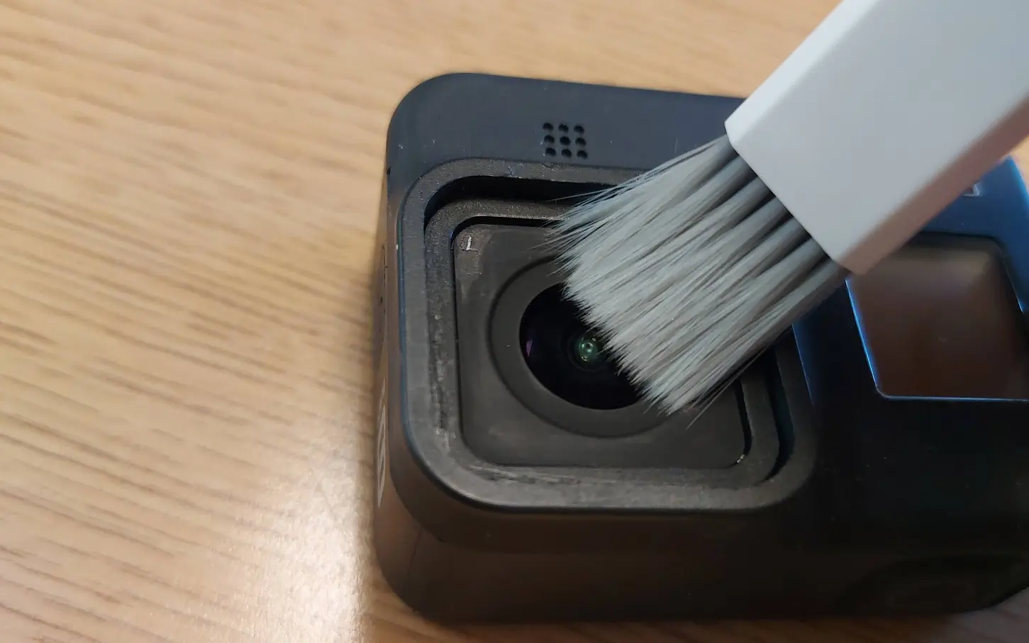
After removing that, there was a fair amount of glass dust and particles lingering on the lens as well as some scuffs. I used a soft brush to kick up the dust out of the cracks in conjunction with a lens pen to buff out the scuffs on the lens.
Brushing Up the Dust
A lot of dust had accumulated in the crack between the edge of the lens and the camera housing, but the brush was able to clean up those cracks nicely.
Using the Lens Pen
I then wiped it down using the cleaning wet and dry wipes that come with the Camera Butter lens kit. After that, I used some dust-removal stickers from an old phone screen protector to get any last remaining particles off of the lens area.
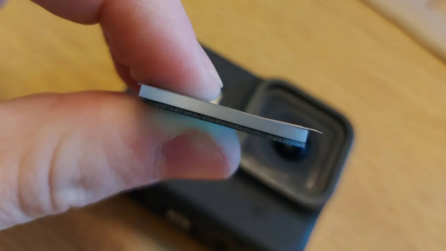
Finally, the camera was ready for a new lens protector. The gorilla glass to be installed is 1mm thick, which doesn’t sound like a lot, but is actually pretty thick when you look at it from the side. The black edge is the thickness of the adhesive used to adhere the glass to the camera.
The Lens Protector from the Side
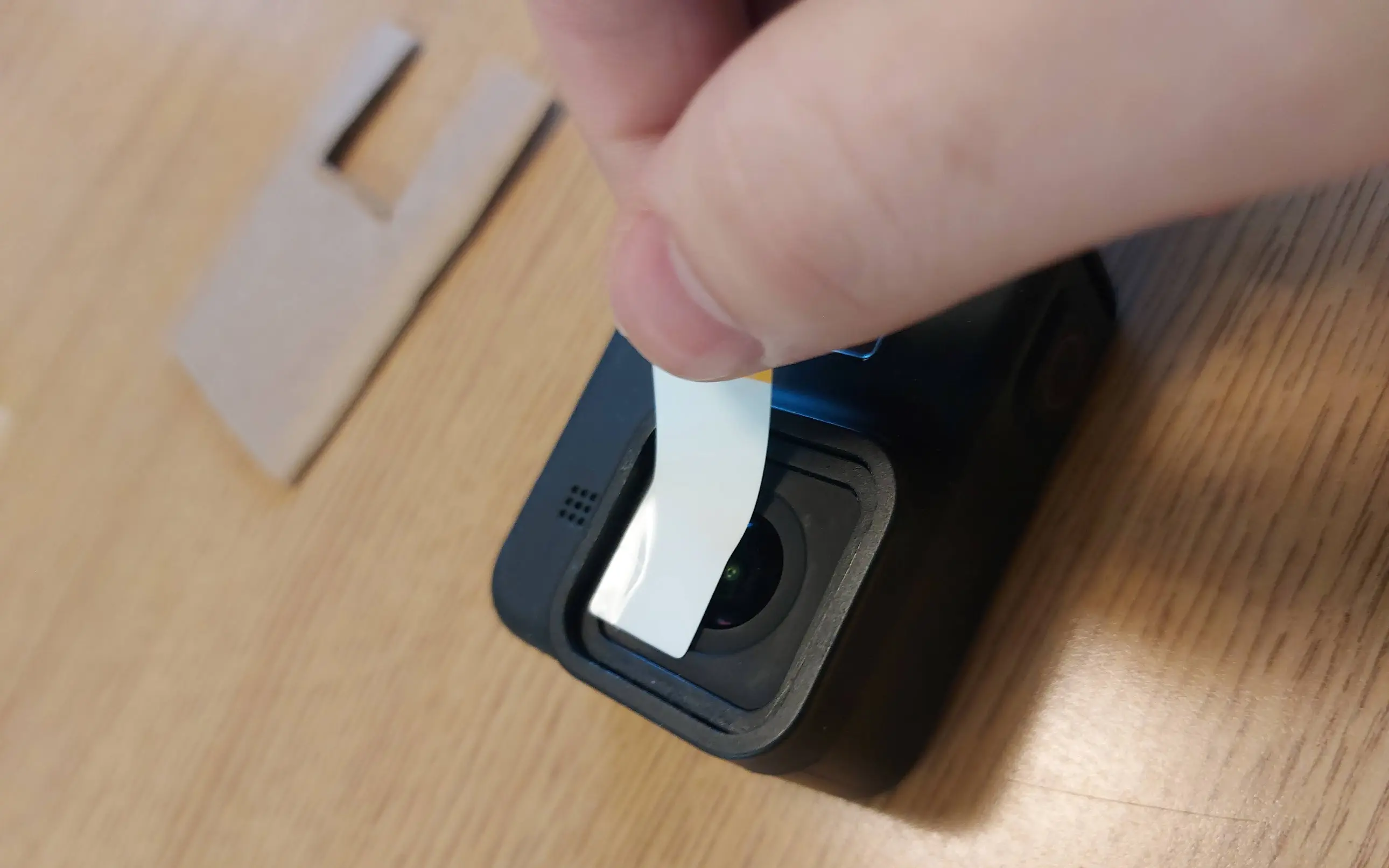
Using two more dust-removal stickers, I positioned the glass over the camera body and then lowered it straight down, firmly pressing the sides in. It was a perfect fit and stuck fast to the surface of the camera. With how thick the glass is, you could also easily grip the sides and slip it into position without the aid of the dust-removal stickers.
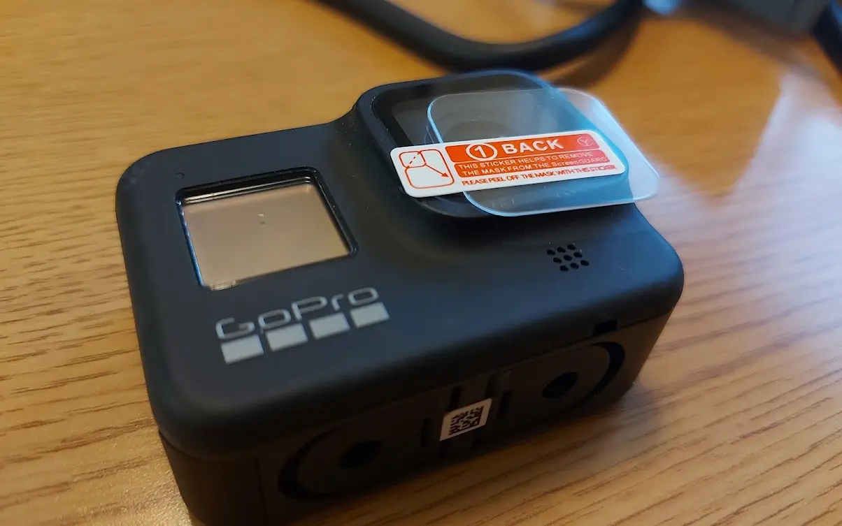
Having seen a decent amount of evidence that the lens protection glass can break, I installed a screen protector on the GoPro much like you would on your phone screen or camera.
Result
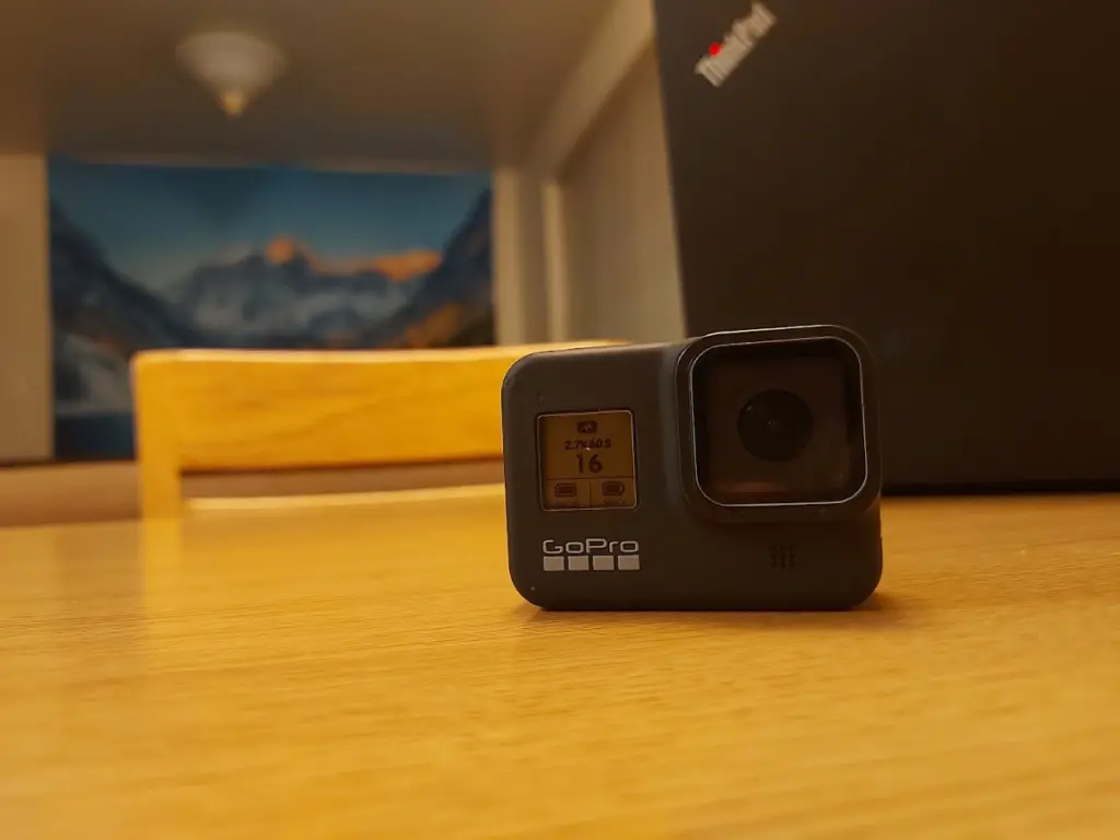
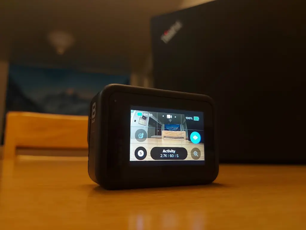
In the end, I ended up with a completely intact and functioning GoPro. Other than the smashed lens cover, everything else on this camera was in good condition. Both screens are flawless and the camera functions operate well.
In this case, it was a success, but it is important to remember that a GoPro that has had its lens broken, probably received a substantial hit and might have other unseen damage. It is important to keep this in mind when looking for one that might be repairable. Before I bought this specific one, I emailed the business and asked them to verify that everything else on the camera was working before I bought it.
At the moment, I am not doing anything I would use the GoPro for, so I have yet to rigorously test it. However, from my limited usage of it, the quality seems good and I am excited to see what it can do.