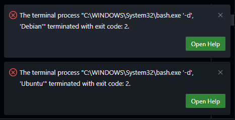
After updating VSCode to May 2025 (v1.101) on Windows, I found that any WSL terminals failed to open. Somehow VSCode was now trying to use “C:\WINDOWS\System32\bash.exe” to run the WSL terminals which was resulting in the following errors:
The terminal process "C:\WINDOWS\System32\bash.exe '-d', 'Debian'" terminated with exit code: 2.
The terminal process "C:\WINDOWS\System32\bash.exe '-d', 'Ubuntu'" terminated with exit code: 2.
The solution is to update the VSCode settings to use the correct WSL executable. The settings are located in the `settings.json` file at C:\Users\<YourUsername>\AppData\Roaming\Code\User\settings.json.
Look for “terminal.integrated.profiles.windows” and if it doesn’t exist, you can add it. If it does exist, ensure that the WSL profile is set to use `wsl.exe` instead of `bash.exe`. Here is the code snippet you need to add or modify in your `settings.json` file:
The story of Mary Magdalene reflects a future day for all of us individually. Mary had found herself in Jesus Christ. He brought out the best in her and showed her her own divine importance. There was no one who had done more for her in her life than Jesus. Suddenly, He was seemingly ripped out of her life only days after His triumphant entry into Jerusalem.
Now she was left alone and her distraught further deepened by the disappearance of His body. She surely must have felt that all had gone wrong and that even the small comfort of mourning had been stolen by someone taking His body away. So depressed and hopeless, she was unable to anticipate the miracle she was about to experience. In her story, when she finally recognizes Jesus’s resurrected face, we ourselves see not only Jesus Christ, but also the faces of those smaller saviors who have passed from our lives.
Because Mary saw Jesus again, we will also be able to see those who have left us. Those parents, spouses, friends, and others who spent their lives with us and built us into the people we are will be resurrected and all will be united. Christ brought all of us with Him back to life. This is the most important doctrine. Because Christ lives, so do we all.
Music: Violin Version of Piano Guys’ O Come O Come Emmanuel
The Murder Ballad of Bishop Henri details the supposed start of Christianity in Finland. The origin of the story has its roots in the twelfth century. The actual ballad appears in the Kanteletar, a collection of Finnish poems and ballads compiled by Elias Lönnrot. It was originally published in 1840 under the name “Kanteletar taikka Suomen Kansan Wanhoja Lauluja ja Wirsiä” (Kanteletar, or Old Songs and Hymns of the Finnish People). The poems and verses that Elias Lönnrot gathered, played an important role in giving definition to the Finnish national identity which later led to Finland becoming an independent state.
A depiction of Bishop Henri (Missale Aboense, the first book ever printed for Finland for usage in Mass)
Summary
The story begins with two brothers, King Eric of Sweden and Bishop Henri of Häme. Henri suggests to King Eric that they go Christianize the pagan lands of Finland. As Henri is traveling through Finland he becomes hungry and goes to the home of Lalli. Lalli is not there, but his wife, Kerttu, is. Henri takes what he needs from the home and leaves money behind. When Lalli returns home, Kerttu tells him that some people came and stole from them. Enraged, Lalli goes out to kill Bishop Henri.
A shepherd and a slave both tell him on the way that his wife lied and he should not kill the Bishop. He ignores them though and eventually catches up to Bishop Henri. Before he dies, Bishop Henri tells his companions, that if he die, to gather his bones in the sled and let the ox take it wherever. Where the Ox eventually tires, there they are to build a church.
After Lalli kills Bishop Henri, he takes his hat and ring. Upon returning home, the shepherd remarks on Lalli’s new ring and hat disapprovingly. Shamefully, Lalli removes the hat and ring. In doing so, he loses tufts of his hair and the ring strips the skin from off his finger. In this way, he receives a punishment from on high for murdering a holy man.
The Moment of Attack, Lalli (left) Bishop Henri (right)
The Ballad
English
Once there grew two children, one grew up in cabbage land, the other was raised in Sweden. The one from cabbage land, he was Henrik of Häme. The one raised in Sweden, he became King Eric.
Henrik of Häme said to his brother Eric: “Let us go and baptize lands, lands that are yet unbaptized, places without priests!”
King Eric said to his brother Henrik: “But the lakes are not yet frozen, the winding river is still flowing.”
Henrik of Häme said to his brother Eric: “I will circle Kiulo Lake, around the winding river.”
He harnessed his horses, placed bridles on them, set the carriages in place, attached the sled runners, fitted the wide shoes on, and the smaller sled planks. He soon set off driving, traveled the path, journeyed on, two spring days, and two nights in a row.
King Eric said to his brother Henrik: “Hunger comes upon us, and there is neither food nor drink, nothing to bite or chew.”
“There is Lalli across the bay, a good place atop the cape There we will eat and drink there we find food”
Upon arriving there, Kerttu, the wicked mistress, spoke with a vile mouth, spouted unkind words.
Then Henrik of Häme took hay for the horses, threw coins in its stead, took bread from the oven’s top, threw coins in its stead, took beer from the cellar, and left money in return. There they ate, there they drank, there they found sustenance; then they left to journey onward.
Lalli returned home. – But Lalli’s wicked wife spoke with her vile mouth, spouted unkind words: “People came here, ate here, drank here, found sustenance here, took hay for the horses, threw coins in its stead, ate bread from the oven’s top, threw coins in its stead, drank beer from the cellar, left sand in its stead.”
The shepherd on the hill said: “You surely have lied; do not believe her!”
Lalli, the ill-natured one, a man of wicked lineage, took his swift horse, and his long spear, and chased after the lords.
The loyal slave said, the faithful worker spoke: “There’s a rumble behind us; shall I drive the horse faster?”
Henrik of Häme said: “If there is a rumble behind us, do not drive the horse faster; just keep the pace steady.”
“What if they catch us or even kill us?”
“Go behind a rock, listen from behind the rock. If I am caught or killed as well, gather my bones from the snow, place them in an ox’s sled, let the ox pull them to Finland. Wherever the ox tires, there a church shall be built, a chapel constructed, where the priest will preach, for all the people to hear.”
The wicked one returned home. The shepherd on the hill said: “Where did Lalli get that hat, the evil man with a fine cap, the bishop’s mitre for a rogue?”
So the man, in his sorrow, reached for the hat on his head: his hair fell in tufts. He removed ring from his finger: his flesh slipped away.
Thus this ill-natured man, the wretched slayer of the bishop, received his punishment from on high, paid the price to the ruler of the world.
Finnish
Kasvoi ennen kaksi lasta, toinen kasvoi kaalimaassa, toinen Ruotsissa yleni. Se kuin kasvoi kaalimaassa, se Hämeen Heinrikki, se kuin Ruotsissa yleni, se on Eirikki kuningas.
Sanoi Hämeen Heinrikki Eirikille veljellensä: ”Läkkäs maita ristimähan, mailla ristimättömillä, paikoilla papittomilla!”
Sanoi Eirikki kuningas Heinrikille veljellensä: ”Ent on järvet jäätämättä, sulana joki kovera.”
Sanoi Hämeen Heinrikki Eirikille veljellensä: ”Kyllä kierrän Kiulon järven, ympäri joki koveran.”
Pani varsat valjahisin, suvikunnat suitsi suuhun, pani korjat kohallensa, saatti lastat sarjallensa, anturoillensa avarat, perällensä pienet kirjat. Niin kohta ajohon lähti, ajoi tietä, matkaeli, kaksi päiveä keväistä, kaksi yötä järjestänsä.
Sanoi Eirikki kuningas Heinrikille veljellensä: ”Jo tässä tulevi nälkä eikä syöä eikä juoa eikä purtua pietä.”
”On Lalli lahen takana, hyvä neuvo niemen päässä, siinä syömmä, siinä juomma, siinä purtua piämmä.”
Sitte sinne saatuansa Kerttu, kelvoton emäntä, suitsi suuta kunnotonta, keitti kieltä kelvotonta.
Sitte Hämeen Heinrikki otti heiniä hevosen, heitti penningit sijalle, otti leivän uunin päältä, heitti penningit sijalle, otti olutta kellarista, vieritti rahat sijalle. Siinä söivät, siinä joivat, siinä purtua pitivät; sitte lähtivät ajohon.
Tuli Lalli kotiansa. – Tuo Lallin paha emäntä suitsi suuta kunnotonta, keitti kieltä kelvotonta: ”Jo tässä kävi ihmisiä, täss’ on syöty, täss’ on juotu, tässä purtua pietty, viety heiniä hevosen, heitty hietoia sijahan, syöty leivät uunin päältä, heitty hietoja sijahan, juotu oluet kellarista, saatu santoa sijahan.”
Lalli se pahatapainen sekä mies pahasukuinen, otti Lalli laukkarinsa, piru pitkän keihä’änsä, ajoi herroja taka’an.
Sanoi orja uskollinen, lausui parka palvelija: ”Jo kuuluu kumu takana, ajanko tätä hevoista?”
Sanoi Hämeen Heinrikki: ”Jos kuuluu kumu takana, elä aja tätä hevoista, karkottele konkaria.”
”Entä jos tavoitetahan taikkapa tapetahanki?”
”Käy sinä kiven ta’aksi, kuultele kiven takana, jos mua tavoitetahan taikka myös tapetahanki. Poimi mun luuni lumesta, ne pane härän rekehen härän Suomehen veteä. Kussa härkä uupunevi, siihen kirkko tehtäköhön, kappeli rakettakohon, papin saarnoja sanella, kansan kaiken kuultavaksi.”
Palasi paha kotia, lausui paimen patsahalta: ”Kusta Lalli lakin saanut, mies paha hyvän hytyrän, pispan hiipan hirtehinen?”
Niinpä mies murehissansa lakin päästänsä tavoitti: hivukset himahtelivat. Veti sormuksen sormesta: lihat ne liukahtelivat.
Niin tämän pahantapaisen pispan raukan raatelijan tuli kosto korkialta, makso mailman valtialta.
Impact
Bishop Henri has gone on to become the Patron Saint of Finland and an enduring symbol of the Christianization of Finland. Lalli, despite his negative portrayal in the story, has also become a recognized symbol of Finnish resistance to foreign influence. Dozens of offshoot stories and legends surrounding the bishop and Lalli have popped up throughout the last centuries.
The current Strava API does not allow for users to request activities in the form of a gpx file. The strava2gpx package for Python uses the Strava API to pull data streams which it then compiles into GPX files, effectively allowing users to get GPX files from the Strava API. This tutorial will cover usage of the strava2gpx package in Python.
Before beginning, it is important to note that gpx files deal with gps data, so Strava activities that do not have gps data, currently will not work with the strava2gpx package. (eg. Yoga, Weightlifting, Pool Swimming, etc.)
Why not use strava.com/activities/id/export_gpx?
The /export_gpx endpoint is useful for some, but is more complicated because accessing private activities requires extra code for authenticating a user and getting the resulting cookies for authentication. This way is much simpler and through the official Strava API.
Will this get heartrate data?
Yes, the strava2gpx package will grab all heartrate, position, power (watts), temperature, and cadence data and encode them into the resulting gpx file using the commonly used Garmin GpxExtensions format.
Installing strava2gpx
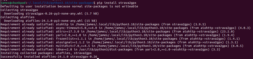
The strava2gpx Python package is available through PyPi and can be downloaded easily by running the following command in your development environment:
pip install strava2gpx
strava2gpx installation in terminal
Getting Strava API Access
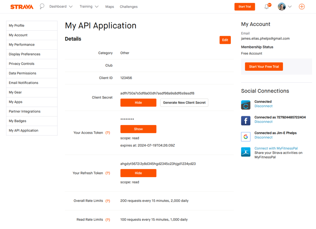
If you already have your credentials for Strava API access you can skip this section. Go to https://www.strava.com/settings/api and if you have not already, go through the steps to create an app there. Eventually, you should get to a screen that looks like this:
The information that we are interested in is the Client ID, Client Secret, and the Refresh Token. Copy those down in a safe spot and don’t share them.
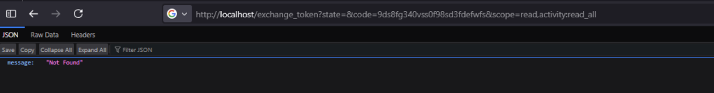
Next go to the following url and replace YOUR_CLIENT_ID with the Client ID that we just copied down.
We are interested in the code part of the url that it redirected to, which in this example is the part that says “9ds8fg340vss0f98sd3fdefwfs.” Copy that down as well. That will be YOUR_AUTH_CODE that we use later.
Now run the following curl command in the terminal, being sure to replace the YOUR_CLIENT_ID, YOUR_CLIENT_SECRET, and YOUR_AUTHORIZATION_CODE with the values we have previously retrieved:
Copy down this new refresh_token for the next section.
Getting the GPX File in Python
Copy the code below into your code editor and replace client_id, client_secret, and refresh_token with their respective values you copied in the previous section from the Strava API. The client_id and client_secret come from the Strava API page and the refresh_token comes from the various web requests we made.
fromstrava2gpximportstrava2gpximportasyncioasync def main():
'''
put in your Strava Api client_id, refresh_token, and client_secret
'''client_id = '123456'
refresh_token = 'adfh750a7s5df8a00dh7asdf98a9s8df6s9asdf8'
client_secret = 'ahgdyt5672i3y8d345hgd2345c23hjgd1234yd23'
# create an instance of strava2gpx s2g = strava2gpx(client_id, client_secret, refresh_token)
# connect to the Strava APIawaits2g.connect()
# write activity to output.gpx by activity idawaits2g.write_to_gpx(11893637629, "output")
if __name__ == '__main__':
asyncio.run(main())
On the line
# write activity to output.gpx by activity idawaits2g.write_to_gpx(11893637629, "output")
you can replace the number (11893637629) with one of your own Strava activity IDs which can be found in the url when looking at them in Strava. (Ex: strava.com/activities/11893637629) This will pull the data from that activity and then compile it into a file called output.gpx. You can change the name of the file by editing the second argument where it currently reads “output”.
Save the python file as strava2gpx.py and run it in the terminal with the following command
python3 strava2gpx.py
When the program has run to completion, you will have an “output.gpx” file in the same directory. This file can be uploaded to other services like Garmin Connect and similar and contains all data like heartrate, power, etc.
Advanced Usage
The package provides an additional function called get_activities_list() which will get a list of all the user’s data and store it in a list of lists where each element is in the following format:
This gives room for bulk processing of activities using custom actions like using date-time to choose what activities are processed or naming them by id and whatnot. Below is an example of calling the function.
fromstrava2gpximportstrava2gpximportasyncioasync def main():
'''
put in your Strava Api client_id, refresh_token, and client_secret
'''client_id = '123456'
refresh_token = 'adfh750a7s5df8a00dh7asdf98a9s8df6s9asdf8'
client_secret = 'ahgdyt5672i3y8d345hgd2345c23hjgd1234yd23'
# create an instance of strava2gpx s2g = strava2gpx(client_id, client_secret, refresh_token)
# connect to the Strava API
awaits2g.connect()
# get a list of all user's Strava activities
activities_list = awaits2g.get_activities_list()print(activities_list[0:5])
if __name__ == '__main__':
asyncio.run(main())
The above code would generate the following output:
[
    ['Legs may be sore', 11910466229, '2024-07-17T11:57:21Z', 'Ride'],
    ['Tall Grass, Hidden Dirt', 11906994862, '2024-07-17T00:10:57Z', 'Ride'],
    ['A little thunder there, a little MTB here', 11898361818, '2024-07-16T01:16:13Z', 'Ride'],
    ['Morning Run', 11893637629, '2024-07-15T11:50:49Z', 'Run'],
    ['Afternoon Yoga', 11880523323, '2024-07-13T19:09:04Z', 'Yoga']
]
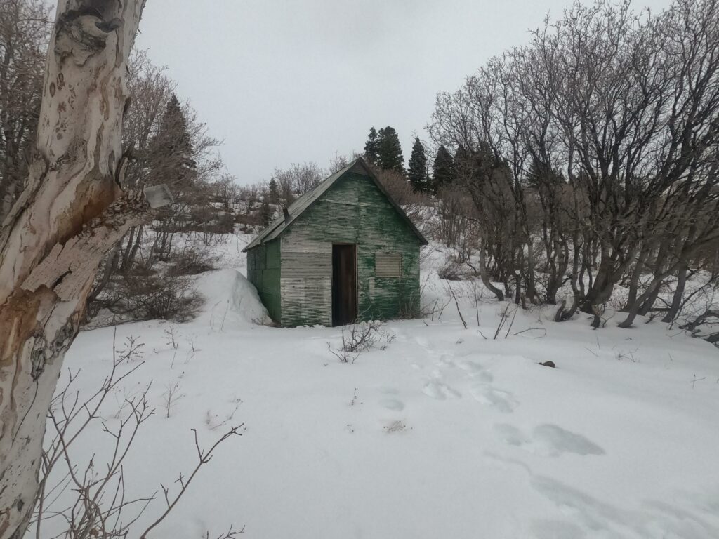
Holme’s Cabin is a lesser known cabin located about halfway up the mountains East of Kaysville. It is accessible starting from the Kaysville East Wilderness Park trailhead and involves climbing 2800 feet of elevation in about three miles making it a very steep hike or run. It is on the ridge South of Adam’s Canyon and North of its namesake Holmes Creek.
Starting the Journey
The closest place to park is at East Mountain Wilderness Park. From there, you can travel up the dirt road until you get to the turn off for the Bonneville Shoreline Trail. Keep north on the trail, going past the bridge until you get to this point pictured below and also marked here on google maps.
At the blue marker pointing left for BST, you will want to take a right to start going up the mountain. The next section of trail is crossed by a lot of other smaller foot paths through the sage brush. A good rule of thumb for keeping on the right path is that you should always be heading up the mountain. There are no downhills and the path does not cut across the mountain to make the way less steep.
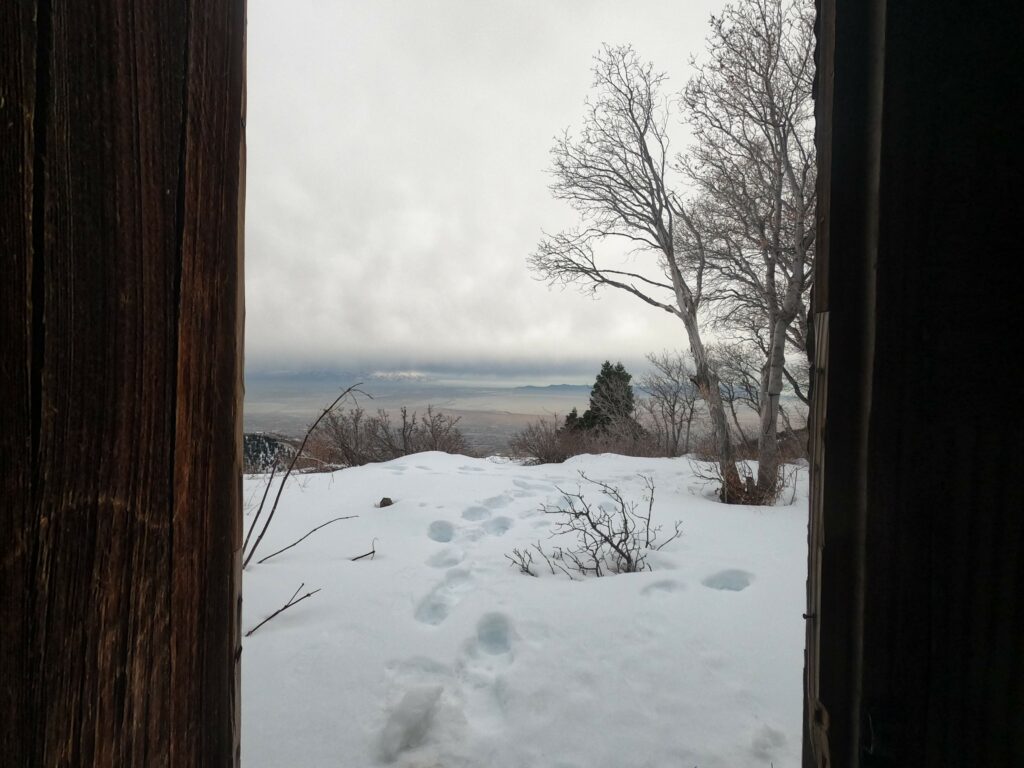
The trek to the cabin is not a lot of mileage, but the steep trail conditions can make it take many hours. If done in the winter, expect considerable snow.
In snowy conditions it is particularly difficult to find the trail since it is not typically well traveled. In this last winter I had to consult maps on my watch very frequently to keep on the right track towards the end of the run.
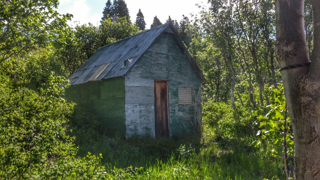
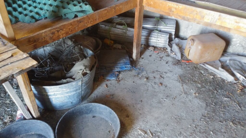
The Cabin
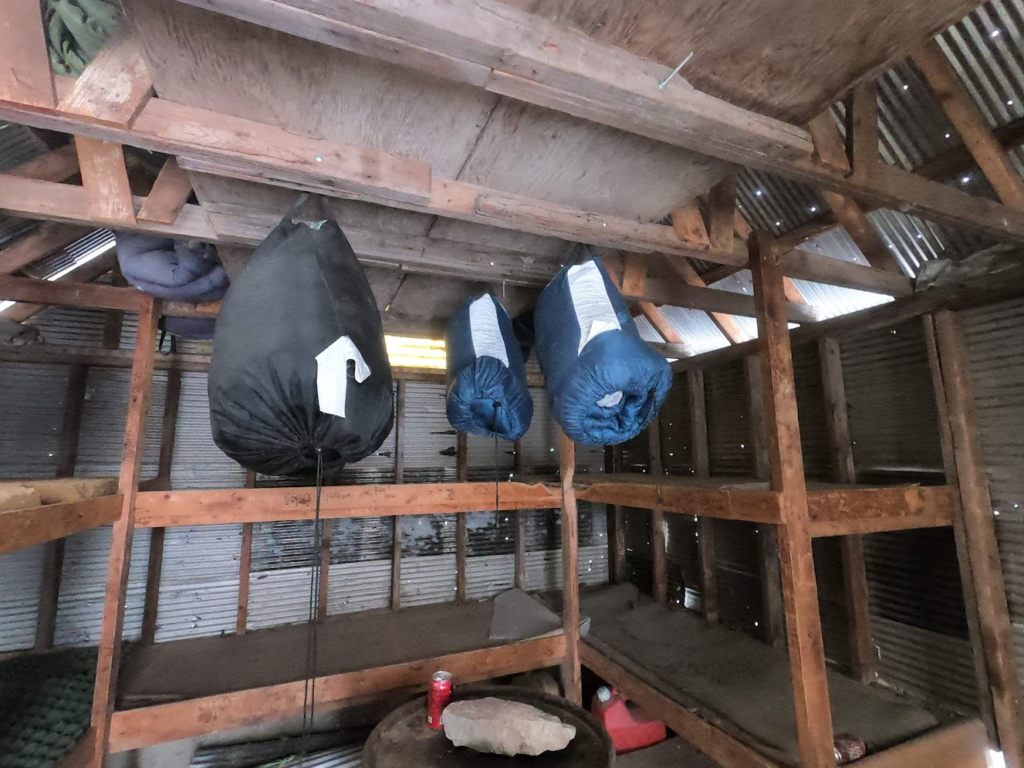
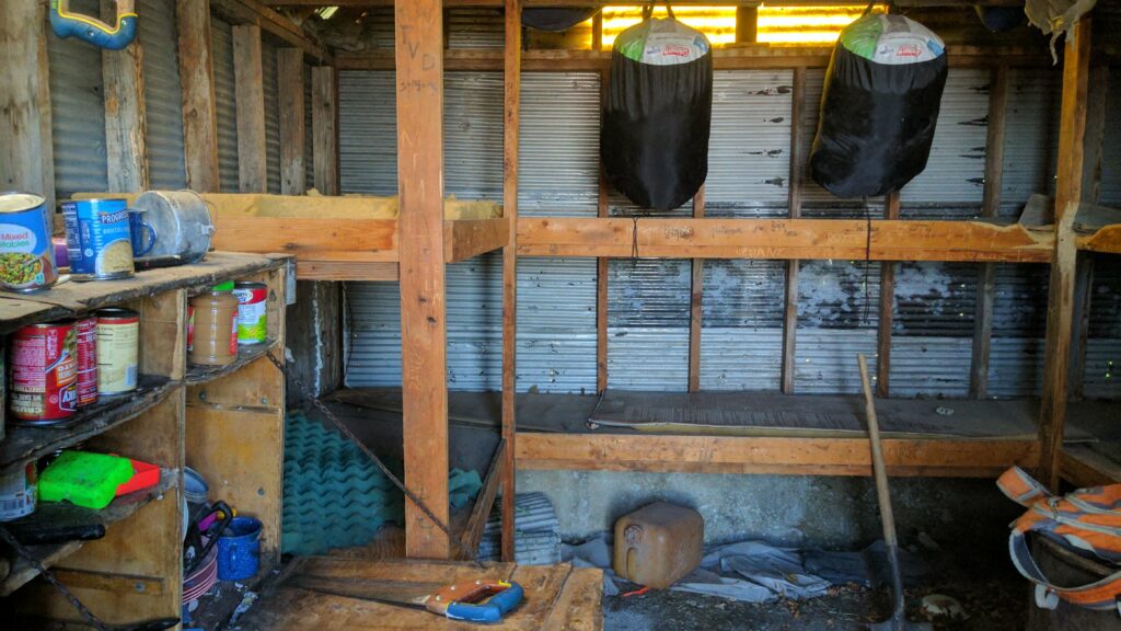
Of the Davis County cabins, Holmes cabin is a sturdy contender. It is not as robust as its neighbor Adam’s cabin, but it is in far better condition than Fernwood cabin which at this point I am guessing has collapsed. Holmes cabin has quite a lot of provisions, though don’t expect free food. The cans of food that were there earlier this year expired in 2014. There are enough supplies to start a fire though if needed. Additionally, there are also sleeping bags hanging from the rafters.
Some Sleeping Bags
Years ago there was a blog post about some winter backpackers who stayed the night at Holmes cabin. That blog seems to have since gone offline, but to my remembrance they appeared to have had an enjoyable time staying the night. It is important to note, that like the other cabins, you do have to worry about rodent droppings. Squirrels and mice are frequent inhabitants of these cabins and they leave stuff everywhere. The first time I visited Holmes cabin, I opened the door and squirrels went scurrying out from everywhere much to the delight of my dog.
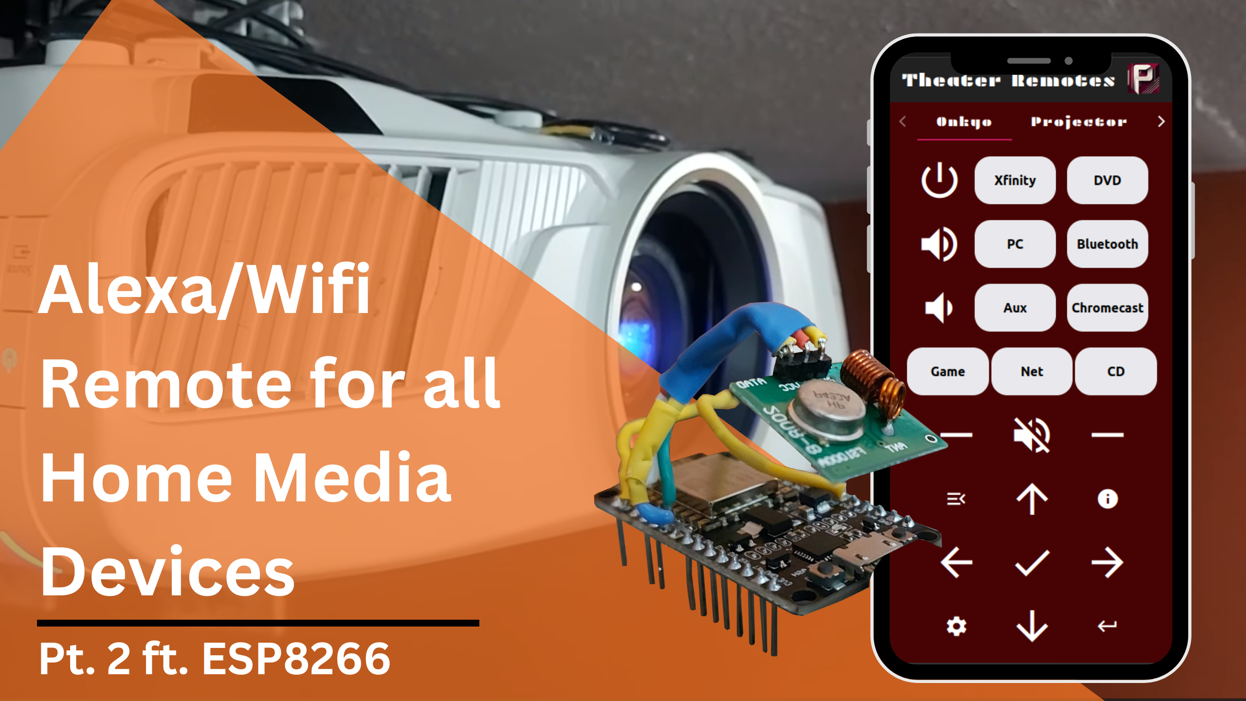
In this second part, we will be going over the programming and network information for this project to control and automate home media devices using Alexa and IR/RC controllers. If you missed part one, the above link will take you to it. The Arduino files and additional simple examples I use can be found at this Github repository.
In this specific article, I will be going over my code and setup for the radio-controlled projector screen and the IR-controlled fireplace. I will show how to configure the network so that the ESP8266 controller can be accessed through Alexa or a custom webapp.
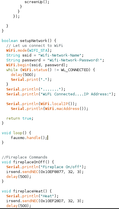
Connect to Wifi
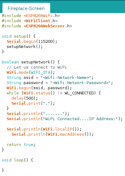
We first need to configure the Wifi connection for the ESP8266. We can create a function called setupNetwork() like below, being sure to replace the <Wifi-Network-Name> and <Wifi-Network-Password> fields with their respective values.
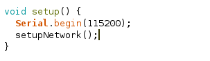
We will call this function in the setup() function so that when the ESP8266 starts up it will automatically connect to Wifi and print out its IP address to the Serial Monitor. Your code should match below:
setup()
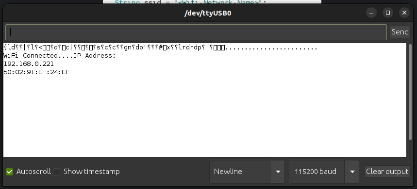
Serial Monitor
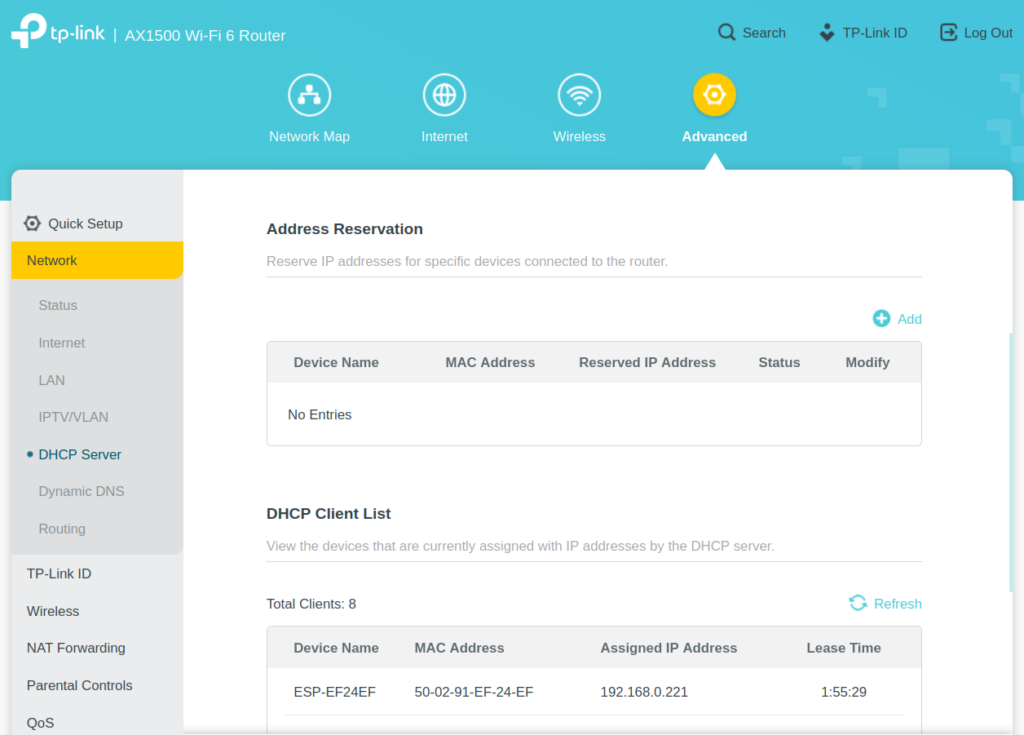
Assign a Static IP
Next we need to set a static IP for the ESP8266 so that your home router does not change its IP address and cause us to lose connection to it. Go to your router’s gateway page or app and find the DHCP settings.
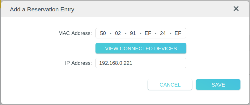
Find the section for reserving addresses and add a new entry using the ESP8266’s IP Address and Mac Address. This will insure that the Router assigns the same IP address to our ESP8266 every time it connects.
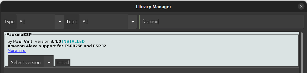
Fauxmo
Install the Fauxmo library using the library manager. Fauxmo will allow us to make a device available on Alexa for turning on or off. It emulates a Wemo device and will look like a smart lightbulb on the Alexa side.
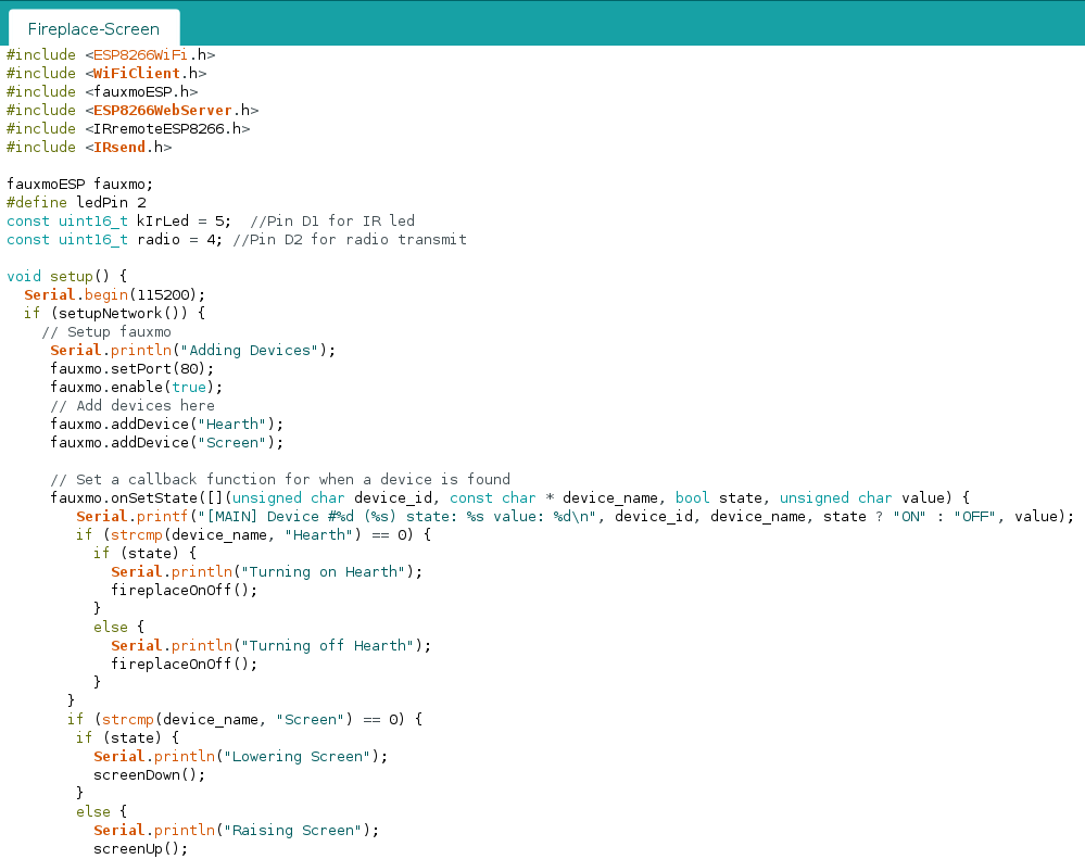
Add #include<fauxmoESP.h> to the top of your arduino file. Declare a variable: fauxmoESP fauxmoESP. Add the following to the setup() function:
void setup() {
  Serial.begin(115200);
  if (setupNetwork()) {
    // Setup fauxmo
     Serial.println("Adding Devices");
     fauxmo.setPort(80);
     fauxmo.enable(true);
     // Add devices here
     fauxmo.addDevice("Hearth");
     fauxmo.addDevice("Screen");

     // Set a callback function for when a device is found
     fauxmo.onSetState([](unsigned char device_id, const char * device_name, bool state, unsigned char value) {
        Serial.printf("[MAIN] Device #%d (%s) state: %s value: %d\n", device_id, device_name, state ? "ON" : "OFF", value);
        if (strcmp(device_name, "Hearth") == 0) {
          if (state) {
            Serial.println("Turning on Hearth");
            fireplaceOnOff();
          }
          else {
            Serial.println("Turning off Hearth");
            fireplaceOnOff();
          }
       }
       if (strcmp(device_name, "Screen") == 0) {
        if (state) {
          Serial.println("Lowering Screen");
          screenDown();
        }
        else {
          Serial.println("Raising Screen");
          screenUp();
        }
       }
     });
  }
}
Make sure to modify the loop() function to have fauxmo.handle(). Also add in your functions for sending IR/RC commands to your devices. Part 1 goes over how to make these commands. These will be used as callback functions for fauxmo to turn on or off our devices. The complete code can be found at this link. Deploy this to your ESP8266 and it will be ready for configuration in the Amazon Alexa app.
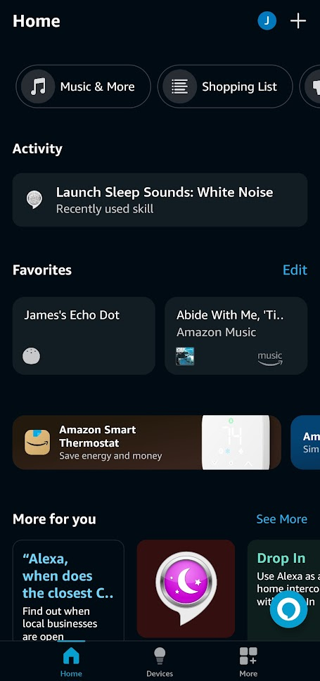
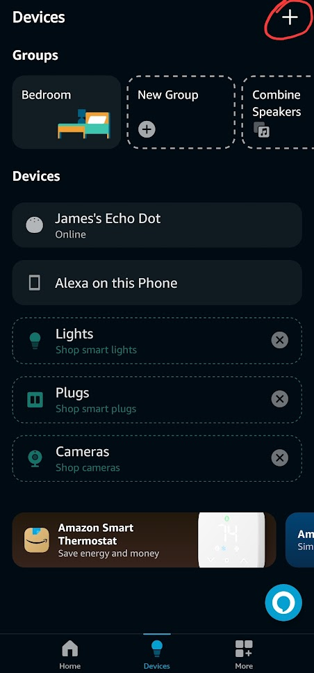
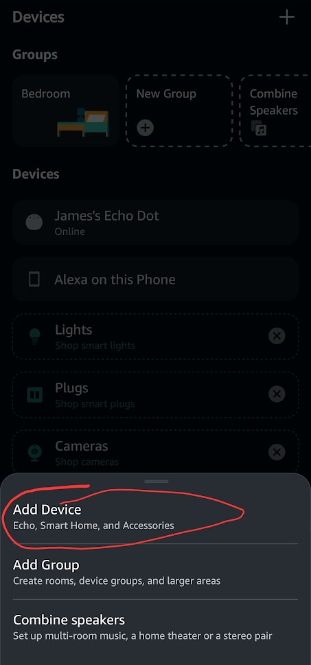
Configuring in Alexa
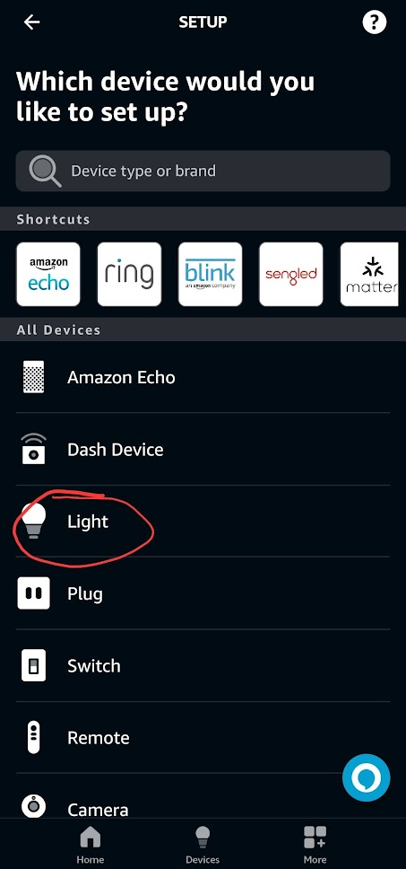
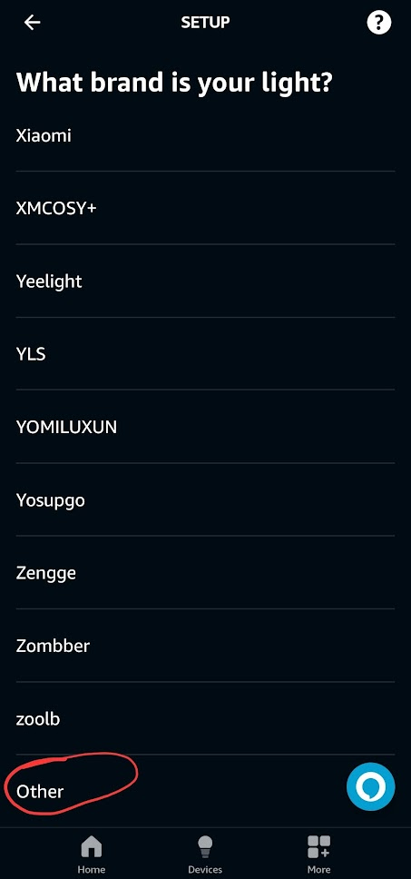
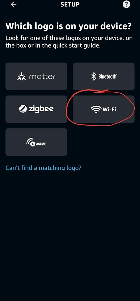
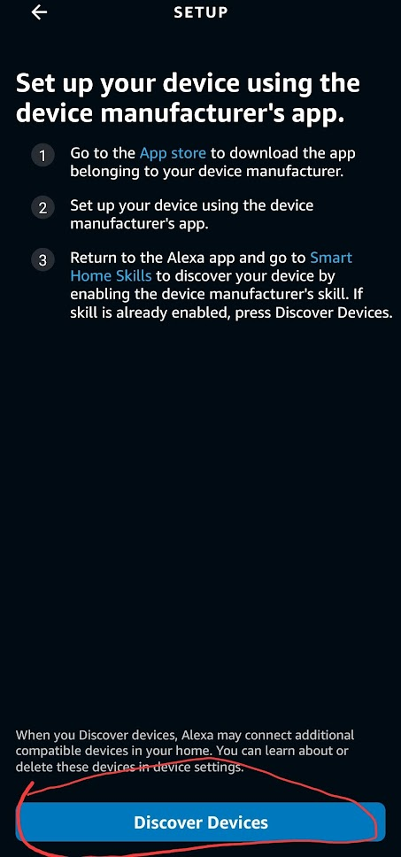
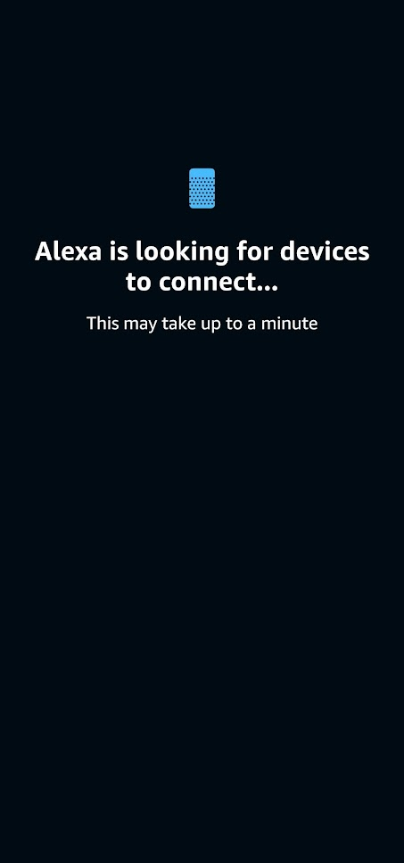
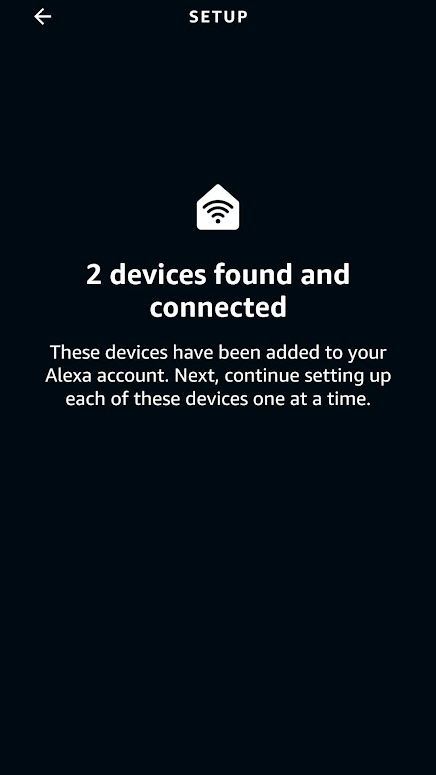
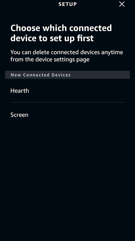
Setting up in Alexa is extremely easy. Once the sketch is deployed to the ESP8266 and the ESP8266 is running fauxmo, it will appear as a smart light when Alexa scans the network for devices. You can ask Alexa to add a device and it will automatically find it or you can follow the screenshots below from the Alexa app.
1
2
3
4
5
6
7
8
9
10
At this point you should be able to ask Alexa to turn on and off your devices successfully. The name of the devices will be the same as the name in the argument to fauxmo.addDevice(“Name”);
Creating a Rest API
The last step in setting up our home media devices is mapping all the different IR/RC commands to endpoints that can be called through network requests.
In the simple example file for sending IR signals, there are three important parts for setting up the Rest API. The first is the routeServer() function in which we will define the endpoints that can be called.
//Server Routing

void routeServer () {
  // Define a default response to the server w/o path
  server.on("/", HTTP_GET, []() {
        server.send(200, F("text/html"),
            F("ESP8266 Controller Basement"));
    });

  // Create endpoints and connect them to corresponding functions
  server.on("/rcDeviceOn", HTTP_GET, RCDeviceOn);
  server.on("/rcDeviceOff", HTTP_GET, RCDeviceOff);
  server.on("/rcDeviceStop", HTTP_GET, RCDeviceStop);

// If endpoint called that doesn't exist, call handleNotFound()
  server.onNotFound(handleNotFound);
}
Each server.on(“/path”, Method, Function) defines an endpoint that can be called with an https request to serveraddress:port/path.
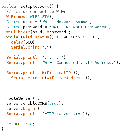
The next important function is setupNetwork() where we previously set up the wifi connection. We need to add a call to routeServer(), enable CORS, and start the server.
boolean setupNetwork() {
// Let us connect to WiFi
WiFi.mode(WIFI_STA);
String ssid = "<Wifi-Network-Name>";
String password = "<Wifi-Network-Password>";
WiFi.begin(ssid, password);
while (WiFi.status() != WL_CONNECTED) {
delay(500);
Serial.print(".");
}
Serial.println(".......");
Serial.println("WiFi Connected....IP Address:");
Serial.println(WiFi.localIP());
Serial.println(WiFi.macAddress());
// call therouteServer()
routeServer();
// enable CORS
server.enableCORS(true);
// start the server
server.begin();
Serial.println("HTTP server live");
return true;
}
The third function is handleNotFound() which is called when an endpoint that doesn’t exist receives a request. It simply sends back to the requesting client a 404: Not Found error.
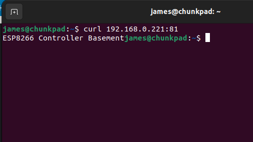
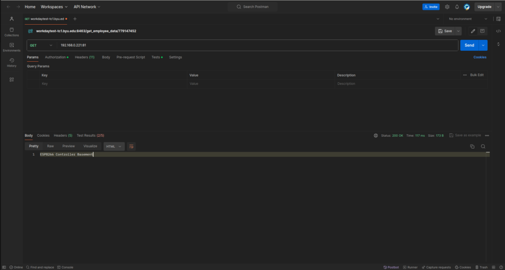
Deploy to the ESP8266 and you should now be able to send requests to your server. If your ip address was 192.168.0.221 and you set the port to 81, you should be able to use the terminal or software like Postman to test your server’s endpoints.
TerminalPostman
Calling from a Webapp
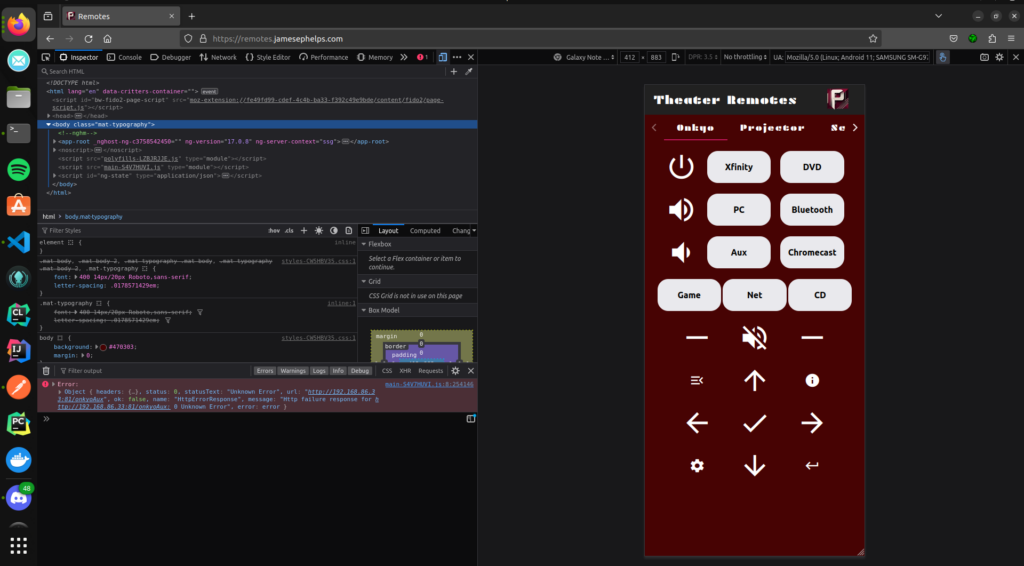
For my use case, I created an angular app that basically consisted of buttons like a remote. When clicked they would call the endpoints on the ESP8266, thus sending the corresponding IR/RC signals to control whatever media device. The webapp runs on an old laptop connected to the home network. The interface of the webapp can be viewed at remotes.jamesephelps.com.
Each button calls a function like this one below to send requests to the ESP8266
The Thinkpad T440P comes with the old Lenovo Slim USB charging port. In my experience, it has only been a source of annoyance as it seems every charger for it stops working after about six months. In this article, I will go through the process of converting the laptop to a USB C charging port. This is a decently well documented mod and is not very difficult to do with a little soldering.
The items required for this mod are a USB C PD trigger module, a soldering iron, a multimeter, and an approximately 500 Ohm resistor. The USB C PD trigger module just needs to provide 20V. This is the module that I happened to use:
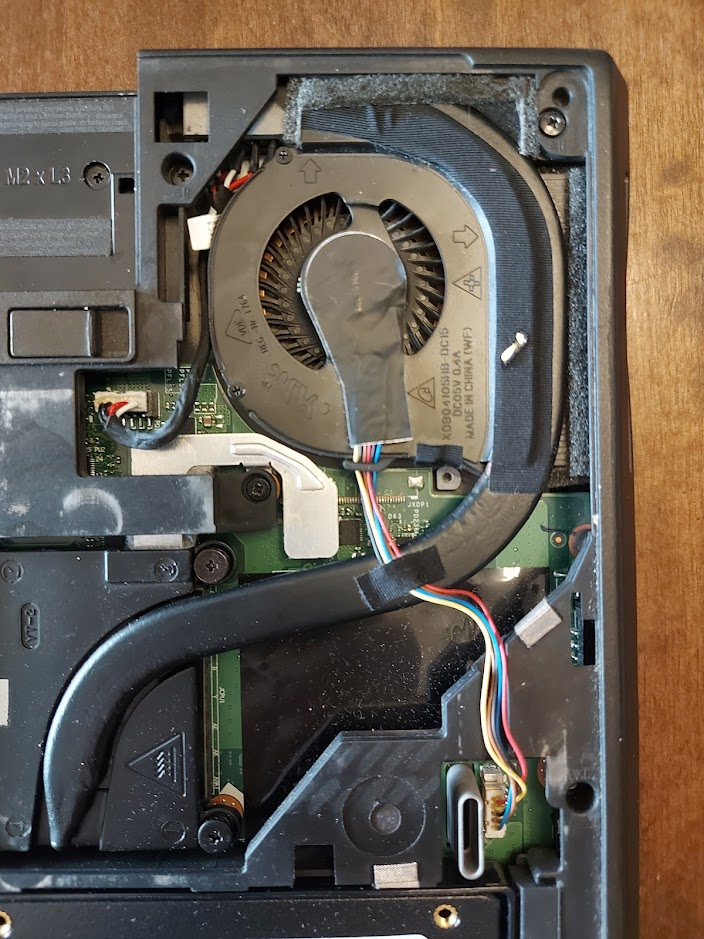
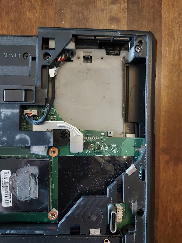
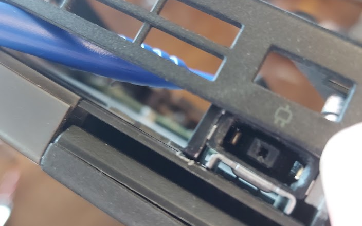
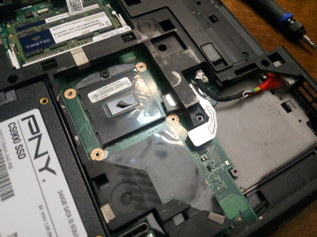
The first step is to remove the old Slim USB charging port. This requires removing the fan from off of the CPU to get access to the port.
Since we have exposed the CPU and messed up the thermal paste, that will need to be reapplied later before the fan is put back on. There are tabs holding the old port into the encasing. Using a thin screwdriver to open up space between the old part and its holdings is the best way to wiggle it out. For me this was pretty difficult to do and involved a lot of gentling, yet violently smashing of the old port so that it would come out.
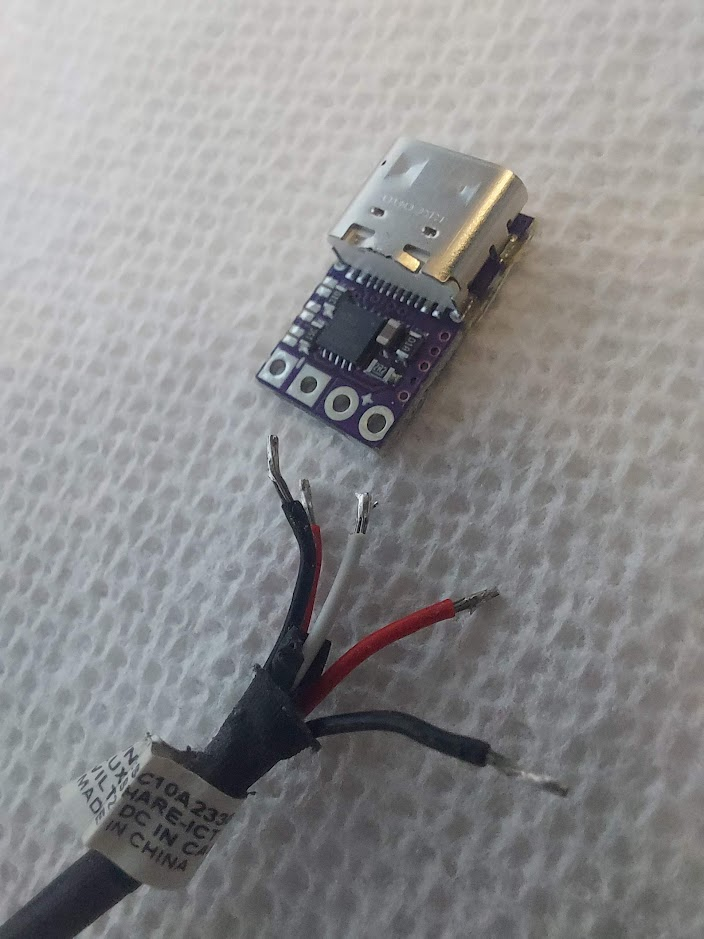
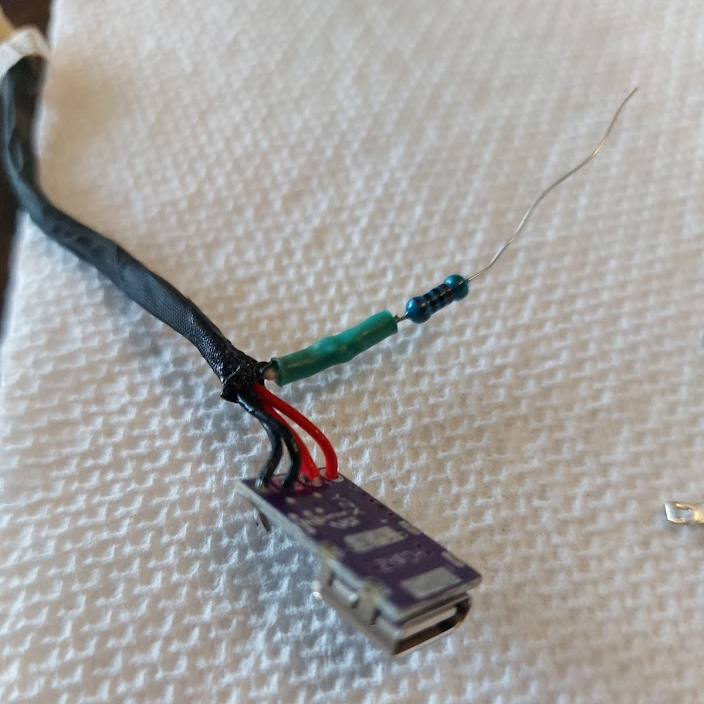
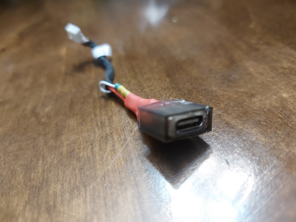
Once the old port is removed, we can salvage the cable from it to build the new USB C port.
The USB C Port
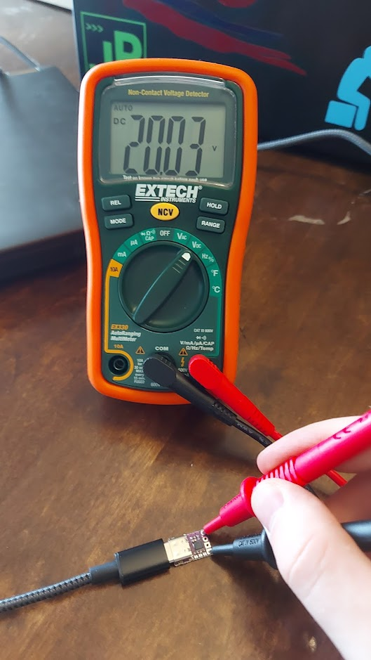
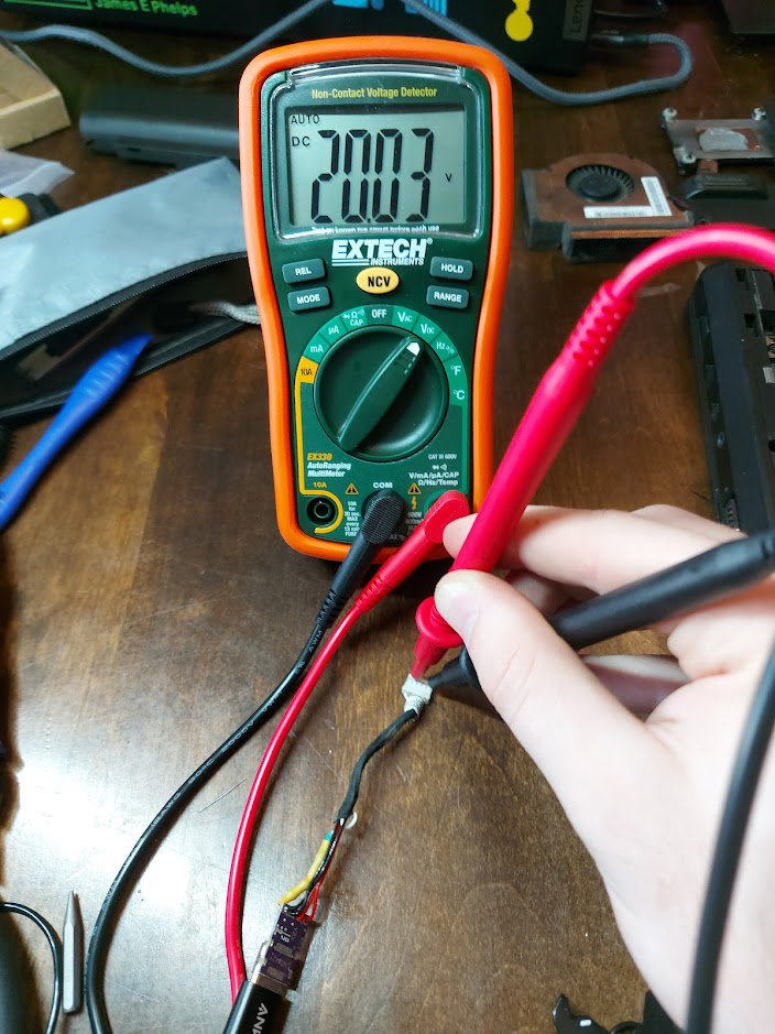
We can use a multimeter to test the output voltage of the USB C PD trigger module to insure that it is 20V.
Once I was sure that the USB C Trigger module had the correct output, I desoldered the Slim USB port from its cables and separated them out.
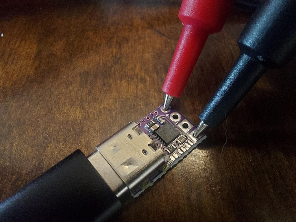
Next, I soldered the black cables to the negative side and the red cables to the positive side. The white cable is a sense wire for detecting the wattage for the computer. It needs to have a resistor attached and then it can be soldered to the negative side with the black cables. The resistor should be around 500 Ohm, it doesn’t need to be exact to work correctly.
Finally, I double checked to make sure that on the end that goes into the motherboard, we were still getting 20V.
A New Port Housing
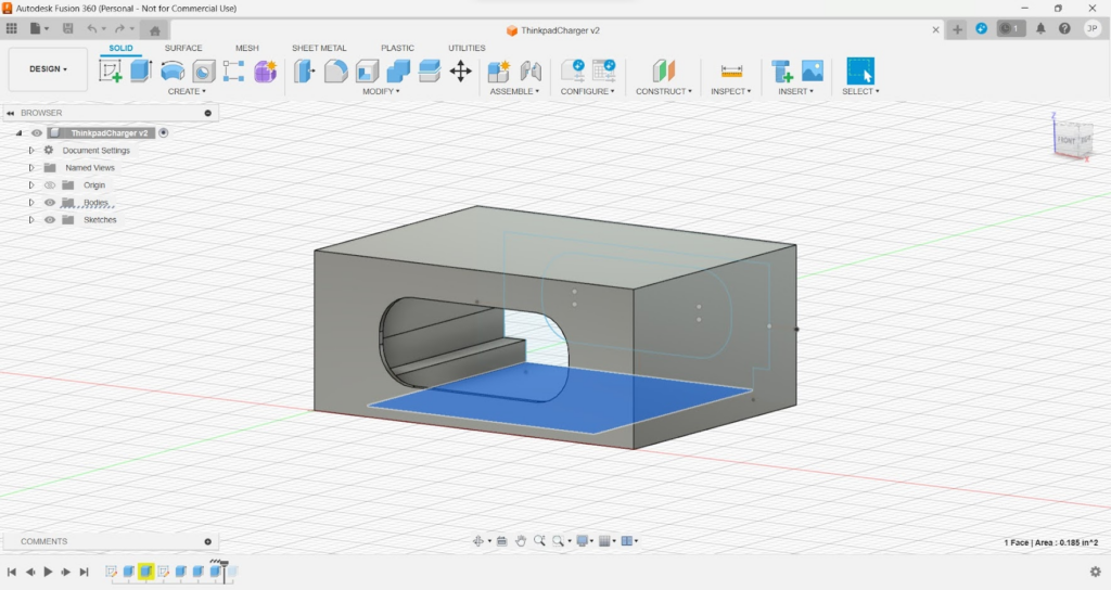
Using a dial caliper, I measured out the dimensions of the hole for the port and the module and designed a new port housing using Fusion 360. If you dual boot like me, make sure to have your time set correctly in your OS for Fusion 360 or it will never load and never tell you why.
It was during the holidays when I did this, so all of the libraries and universities around me with 3D printers were closed. I opted to use a 3D printing service online which ended up taking over a month to print and then ship my part to me.
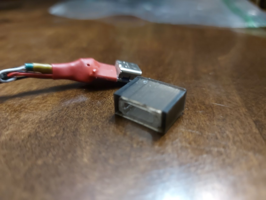
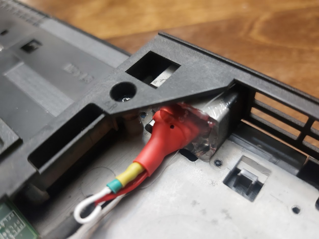
I put the port inside the housing using hot glue. The hot glue worked okay, but I would have preferred something a little bit stronger.
Putting it all together
I slid the port into the laptop and then filled up the back with hot glue to hold it in. Again, the hot glue doesn’t feel super sturdy, but it has held it in so far.
Lastly, I cleaned up and reapplied the thermal paste before putting the fan back onto the CPU.
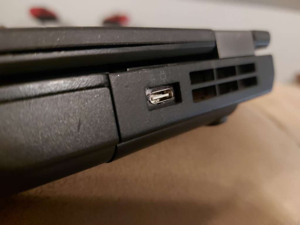
In the end it worked and the port does not look terrible. It was a little bit of a squeeze to move the cable over so the fan could go back in. Might be a good idea to make sure the back of the port is not too rigid. If I could do it again, I would probably find an alternative solution to hot glue for holding it in. In theory, this is supposed to go with a 90W charger, but if the laptop is off it will slowly charge alright with a lower wattage.
In this series of articles I will be going over my efforts to create a home media control system using a couple ESP8266’s. The end result will be a fully automated theater setup through Amazon Alexa and a webapp built in Angular. This series will go over setting up an ESP8266 to read and transmit both IR signal and RF signals, making controllable smart devices for Alexa, creating a locally hosted webapp for remote control, and the steps to properly configure a home network.
The following video shows the end result using Alexa to turn on all devices in the home theater. This setup includes a video streaming box, surround system, projector, radio-controlled projector screen, and an electric fireplace. The specific device information is listed under the video.
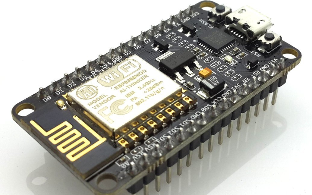
For this project, I will be using Nodemcu ESP8266 Development Boards that I purchased off of Amazon. These can be found for cheaper from websites that ship from China, but I was on a time limit since I will be returning back to school soon, so I went the faster Amazon route. I specifically used the HiLetGo models which seemed to work. Of the three I bought, one arrived dead, but the other two were fine.
The ESP8266 is a microcontroller that can be easily programmed through a micro usb connection using an IDE like Arduino. The ESP8266 is special because it has wifi capabilities and a very strong community behind it, making resources for it readily available on the internet.
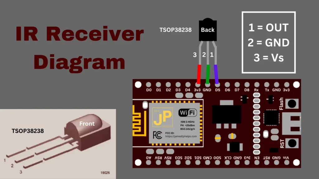
In addition to the boards, I also purchased an IR Receiver and LED from Adafruit. These will allow us to read Infrared signals from the remotes and then be able to replicate them ourselves on our ESP8266 to emit the same signals as our remotes. I also got a tiny breadboard from Adafruit to allow for easier prototyping before I permanently soldered components to the ESP8266’s.
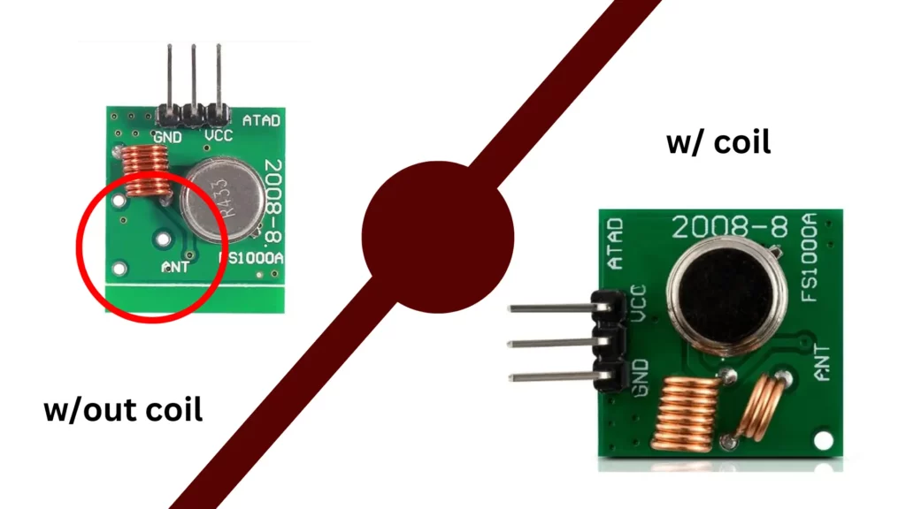
Lastly, I also ended up needing to get a 433 MHz RF receiver and transmitter for the projector screen. The projector screen is controlled by an RF remote which emits radio signals. When searching for such a receiver and transmitter, I found many transmitters that seemed to be missing a coil on Amazon as shown below.
What effect this has is outside of the scope of my knowledge, but several reviewers indicated the coil is necessary for proper functioning, so I was sure to buy one with the coil. For me, all the product listings when I first searched on Amazon were missing this coil. I had to search for a while before I found one that seemed to actually have the coil.
Receiving IR Signals
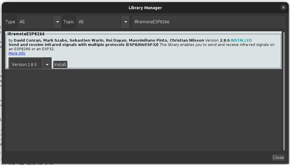
Most devices are controlled using IR remotes which emit an IR signal that the device can pick up on using a receiver. To get our needed signals, we will connect the IR receiver to our ESP8266 board and then record data that it picks up from our remotes. We will use a library called IRremoteESP8266 that can be found in the Arduino libraries to understand the data that the receiver picks up.
In Arduino, go to Tools>Manage Libraries… (Ctrl+shift+I). Search for “IRremoteESP8266” and install the only one that pops up.
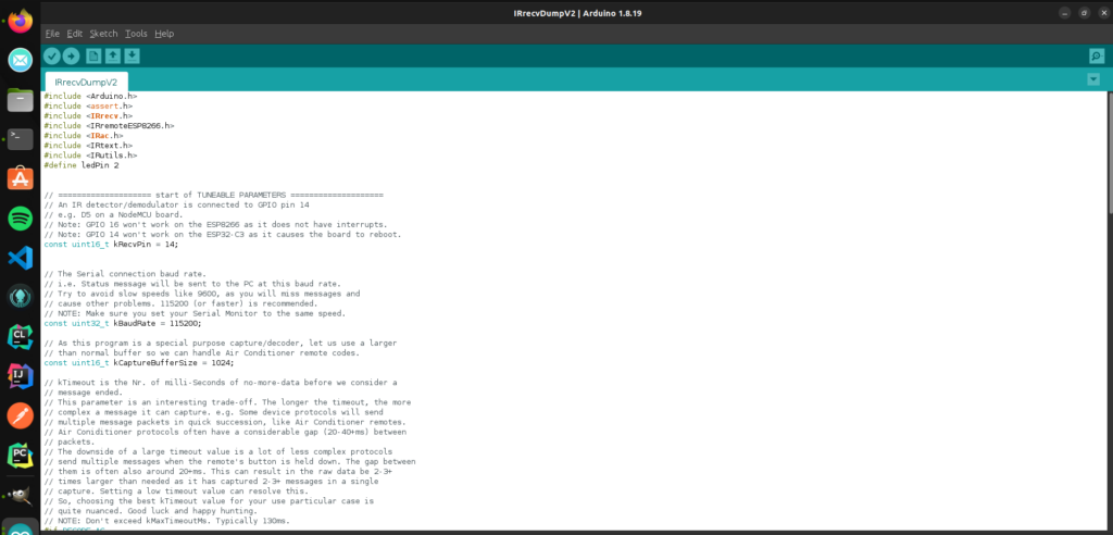
Now go to your file manager and find where Arduino is installed. From there go to libraries/IRremoteESP8266/examples/IRrecDumpv2 and open in Arduino the IRrecDumpv2.ino file.
This sketch allows us to receive codes from the remotes on the ESP8266. The top section has a couple of parameters you can edit to fine tune your setup. It is likely you will not need to modify this at all. For mine to work, I had to change kMinUnknownSize to a very high number, because I was picking up random numbers on my receiver.
Deploy this sketch to your ESP8266 by pressing the arrow up in the top left. This will pop up a terminal, displaying the status of the compiling process and then the write process. Now we need to actually connect the IR receiver to our ESP8266.
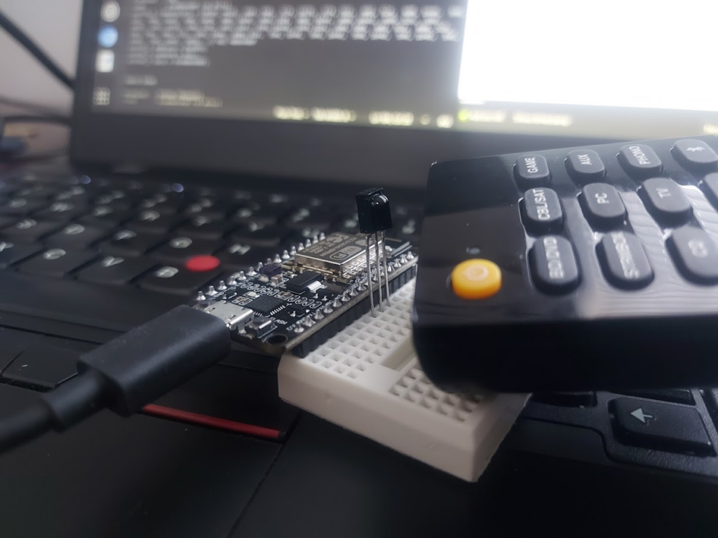
I was able to use the breadboard and just plug the receiver in since this is a super simple setup. Once the receiver is connected, keep the board connected to the computer, and open the serial monitor in Arduino.
I had to put the remote pretty close to my receiver for it to pick it up for some reason
If successful, each time you press a button, output should show up in the serial monitor that looks like this:
Go through each button on the remote that you want and record what it outputs to the serial monitor. We will use the code (ex. 0x10EF8877), the protocol (ex. NEC), and the amount of bits (ex. 32 Bits) when we send a signal to the remote. Later when we write the code to send the signals it will be done similar to this this:
I keep getting code 0xFFFFFF in the serial monitor
In the NEC protocol, 0xFFFFFF is the repeat command and simply means that whatever the last command sent by the remote is needs to be repeated. Just ignore these and keep sending signals with the remote until you get a code that is not 0xFFFFFF
I am only getting question marks in the serial monitor
Make sure that your baudrate in the serial monitor is set to the same as was set in the above sketch (probably 115200). If the baudrate does not match, you might just get a bunch of question marks in the serial monitor.
I am just getting continuous random output in the serial monitor
Check to make sure that the wiring is correct. If it is and the problem persists, try setting the kMinUnknownSize variable in the sketch to 10000 and re-deploy the sketch to your esp8266.
Sending IR Signals
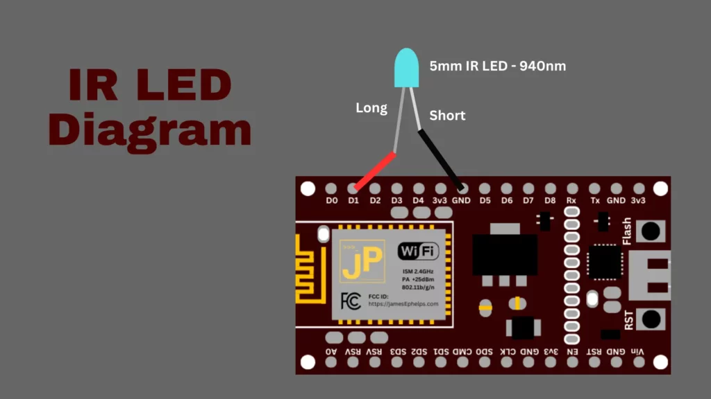
To send the signals that we recorded, we must first wire the IR Led up to our ESP8266. The following diagram shows the proper way to connect the Led to the board.
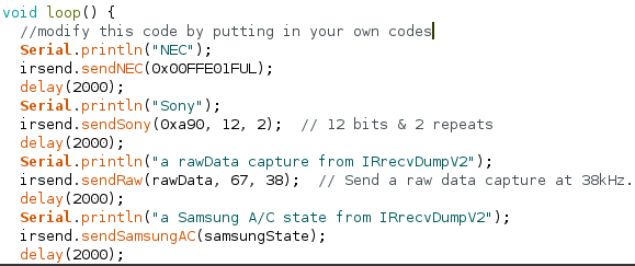
This should be pretty easy using a breadboard and some wires. To test if your remote signals work, navigate back to your Arduino folder like previously and go through the folders: libraries/IRremoteESP8266/examples/IRsendDemo and open the IRsendDemo.ino file. If you followed the diagram above, you will need to change kIrLed variable to 5. Now, put your own codes in the loop() so that your ESP8266 will continuously send your signals so we can test them. Deploy this new sketch to your board.
If you want to check if your board is sending any IR signals at all, you can look at the IR led through your phone’s camera. If it is working, you will see distinct purple flashes. If you have the correct codes, it will now be able to interact with your controllable devices just like your original remote does.
Receiving RF signals
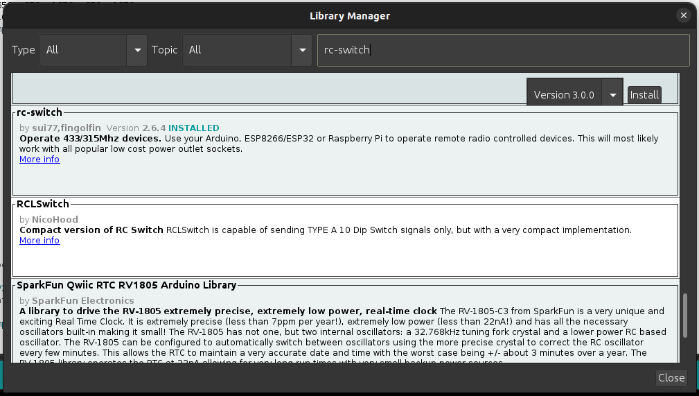
If you have a device that is radio controlled by 433MHz, we can use the rc-switch library to decode and transmit radio signals. Go back to the library manager (Ctrl+shift+I) in Arduino and search for rc-switch to install. Make sure to install the one by sui77 and fingolfin.
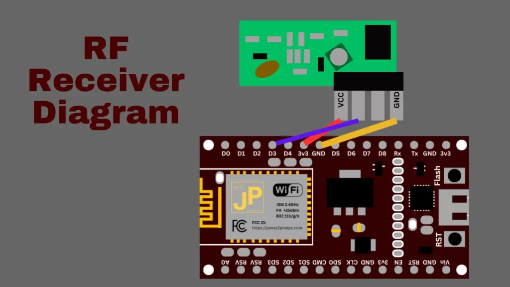
Next, go to the Arduino folder and navigate through the following folders libraries/rc-switch/examples/ReceiveDemo_Simple/ and open ReceiveDemo_Simple.ino. This sketch allows us to use the RF receiver to get codes that represent the radio signals from our RF remotes. Deploy this sketch to the board. (You may need to adjust the baudrate if you are using a different rate. This is done in the code at Serial.begin(9600) where 9600 is the baudrate) Now, wire up the receiver as shown in this diagram.
If done correctly, you should now be able to press buttons on your RF remote and data will show up in the Serial Monitor. There are three things we’re are looking for: a code, a number of bits, and a protocol number.
6582737
24bit
Protocol: 1
Transmitting RF Signals
To test if the RF signals we picked up work, we can use the provided SendDemo.ino file in the folders Arduino/libraries/rc-switch/examples/SendDemo/. If you got the output from the previous example, you would test it by adding a line of code to the loop() function like so:
The wiring for the transmitter is done as follows:
If you are using this same setup, you will need to change the line in the sketch mySwitch.enableTransmit(4); so that it uses pin 4 which is D2. Deploy the sketch and you should now be able to control your RF device using the ESP8266.
In summary, following these steps, you should be able to get all the data from your remotes and devices that you will need in order to control them. In part 2, we will go over actually doing the programming so that voice assistants like Alexa or a custom webapp can send these signals to the devices.
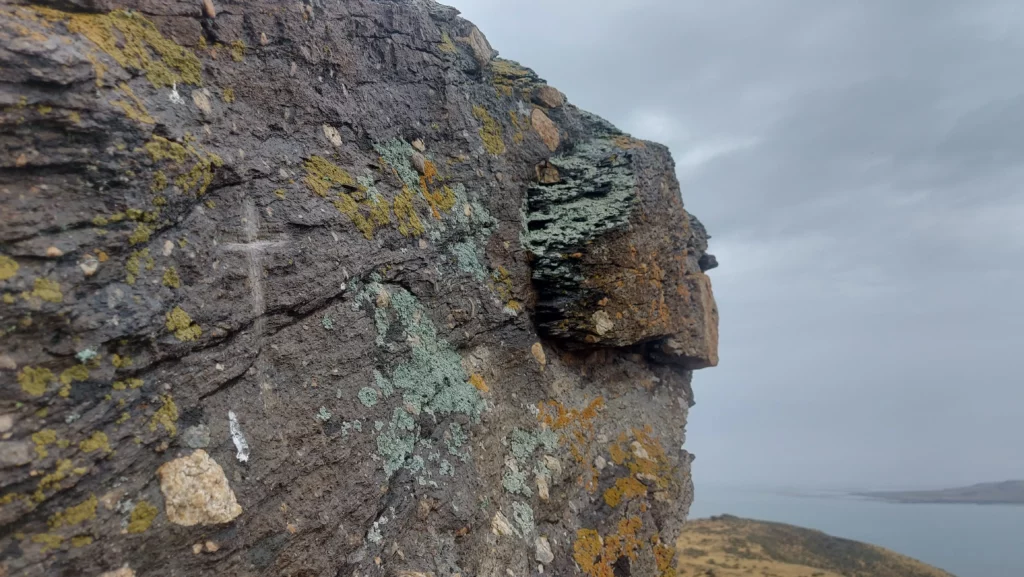
Despite being a relatively sparse wasteland, Fremont Island has a decently interesting history. Located 6 miles northwest from the far more popular Antelope Island, Fremont Island is a standing record of the island’s few visitors through the centuries. Hundreds of years ago, Native Americans used the island for different plants and resources. They left behind a few artifacts including some petroglyphs. In the preceding two centuries, white explorers and settlers have added their mark on the island. Explorers John C. Fremont and Kit Carson visited the island in 1843 and Kit Carson etched a cross into a rock that is still visible today.
Kit Carson’s Cross on Castle Rock
After the pioneers arrived in the Utah area, the island was used for various purposes including mining, sheep herding, and once Brigham Young even exiled a grave robber to the island for his crimes. The only known long term residents of the island have been the Wenner family who owned the island from 1886 to 1960. Uriah Wenner, a Salt Lake County judge, bought the island from the Union Pacific in hopes that the salty air would help him handle his tuberculosis. (History of the Wenner Family)
Today the island is owned by the State of Utah and is publicly accessible by foot or biking. Motorized vehicles are not allowed and camping is also prohibited in order to preserve the island.
Getting to the island
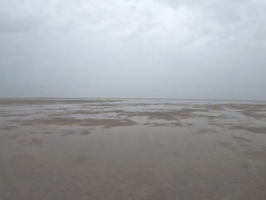
I made my journey to the island mid-August 2023. That day, there were heavy rainstorms sweeping across the lake. As I drove across the causeway, rain pounded my vehicle and I started to wonder if I would be able to make the run. Visibility was low and I could not see the island, just a wall of white to the north. I parked at the U.S. Army Ranger and Air Force Memorial and ran two miles back on the causeway.
I hopped off the causeway and started running on the sandbar which was starting to fill up with water. Every step I sank into the increasingly muddy mess. The mud suctioned around my feet making it good work to pull them back up with every pace. The smell of the Great Salt Lake resembles rotten eggs and the mud seemed then to be the very essence of it mixed with slimy somethings and decaying organic matter. Large swaths of gnats huddled on the sand, grounded by the weather.
Had I not had a GPS device I would not have been able to discern the correct way to go because of the heavy rain. The island was definitely farther West than I had been thinking, but checking in every now and then with the GPS allowed me to keep heading the correct way. Usually, the island is easily visible so this is not a typical problem when making the trek.
A view of my surroundings
The obscured and uniform view in all directions was actually kind of a pleasant environment to run in. After an hour of steady plodding through the mud, the intensity of the rain started to abate and visibility started to increase.
Because of the previous lack of visibility and rising water, I did end up running slightly off where the sandbar is supposed to be and into deeper waters for a while. On a sunny day this would be easily avoidable. The last mile to the island was me splashing through the water and trying not to fall. Though at this point, I could not get any wetter.
Trudging through the last part
I entered the island from the southeastern side where I was greeted by a trail camera monitoring the island’s visitors. There is a dirt road running along the edge that leads up to an old cabin structure built by Justin Barrow, a previous owner of the island who tried to make a private hunting business by bringing in exotic animals in the 2000’s.
Justin Barrow Cabin
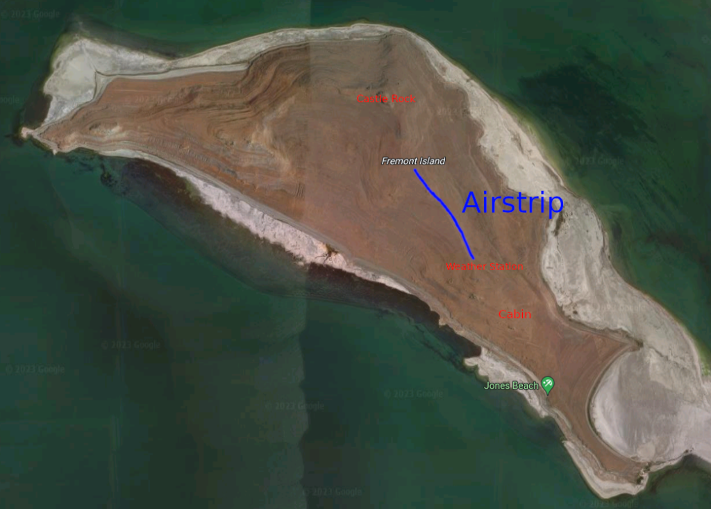
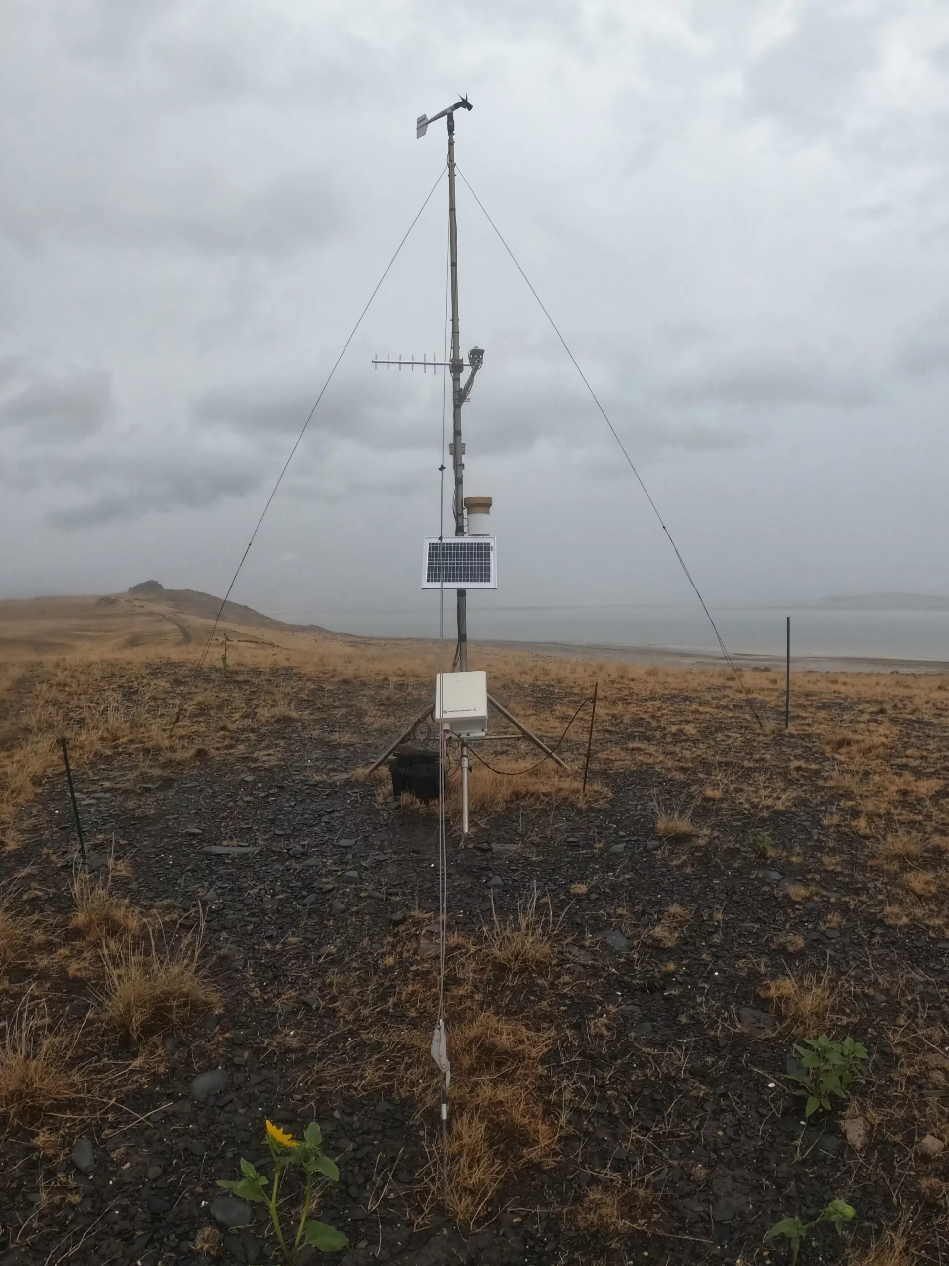
From the cabin, I ran up the road north to the top of David E. Miller hill where the University of Utah has a weather station. The next stretch from there is the island’s airstrip along the central ridge of the island.
Basic Map of the IslandU of U Weather Station, David E Miller HillWindsock at the Airstrip
All in all, the total running distance from Antelope Island to Castle Rock was about 12 miles. The final climb up to Castle Rock is very steep and may involve some clambering on all fours depending on the side of the hill. I approached from the east side and left on the north side. In my estimation there is not a side of the hill that is any easier than the others to climb. All are pretty steep.
Castle Rock stands out well and Kit Carson’s cross is easy to locate on the east side of the rock. This marks the highest point of Fremont Island and provides a view of the surrounding lake and mountains.
During my stay on the island, the rain had stopped and the water levels on the sandbar had fallen. On my return across the sandbar, I had pretty good weather for about a mile. The bugs took advantage of this for a little bit and were quite a nuisance, apparently attracted to my head. Along the way back I noticed there seems to be these wooden posts driven in the ground at various intervals marking the way to the island. If there is any bad weather though, they are pretty much invisible.
Eventually the rain returned, although much lighter, but accompanied by very fierce winds. The last few miles getting off of the sand were very muddy and the unstable ground was starting to take a toll on my legs. All in all, the trip was a total 24 miles and well worth it. I will definitely return to the island, but probably in better weather. There is still more things to find and areas to explore.
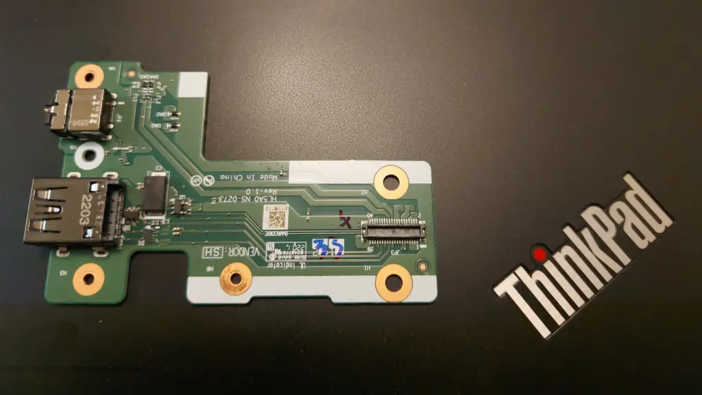
Last year I was able to snatch a refurbished Thinkpad l15 Gen 2 from Lenovo for $200. Recently I noticed that the USB port on the right didn’t actually work. Upon further inspection I found the pins inside were sunken. After some attempts with tweezers to reposition them so they would come into contact with USB devices, I succeeded in mangling them even worse, insuring they would never work again.
Fortunately, the damaged USB port was the on the right which is part of a USB and 3.5mm audio board, separate from the motherboard. Had it been on the other side, it would have required a motherboard replacement to get a working USB port again. After watching on Ebay for a good price, I was able to find a replacement USB Audio board for $8. For reference, the part number is 5C50S73039.
Installation
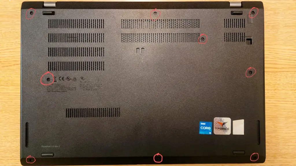
First, remove the bottom panel. There are 9 screws that need to be loosened. They will not come out completely, because the bottom panel holds onto them so they don’t get lost.
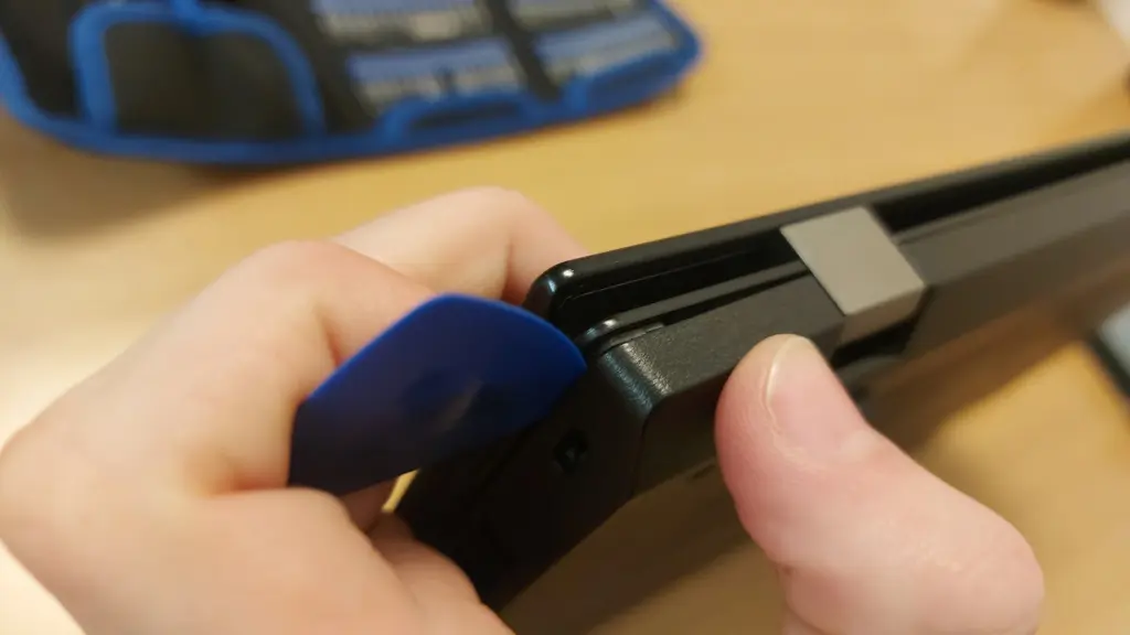
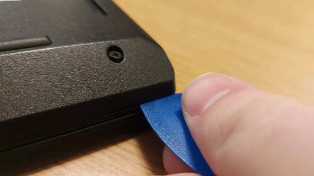
Once the screws are loosened, we need to pry open the hooks holding it onto the laptop. Insert a small, non-metal edge (a credit card could work) into the seam between the panel and laptop. Go around the entire perimeter of the laptop, gently popping it open. You should feel and hear a pop as each hook is undone. Make sure there is no micro sd card in the slot or you won’t be able to pry the panel off.
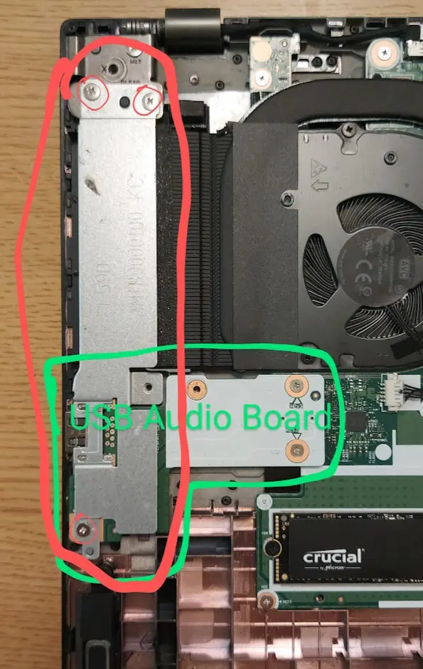
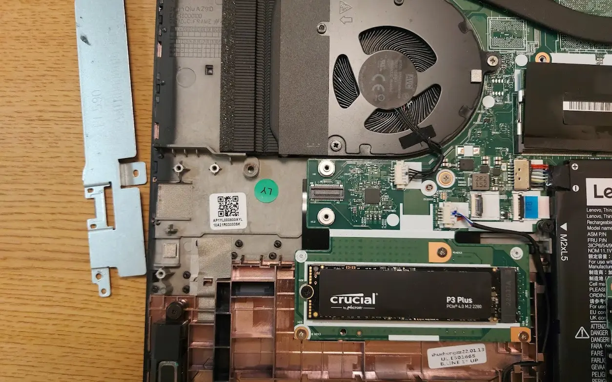
Once the panel is off, we need to remove the metal cover on the side. This is covering the USB Audio board. Mine had three screws holding it in. After removing the screws, the metal panel should come right off, revealing the USB Audio board.
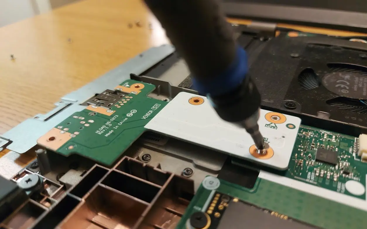
Remove the screws from the USB Audio Board (mine had only three screws again). Then you should be able to gently lift it straight up. It is plugged into the motherboard on the underside, so there will be a little bit of resistance.
Removing the ScrewsThe Laptop with the USB Audio Board Removed
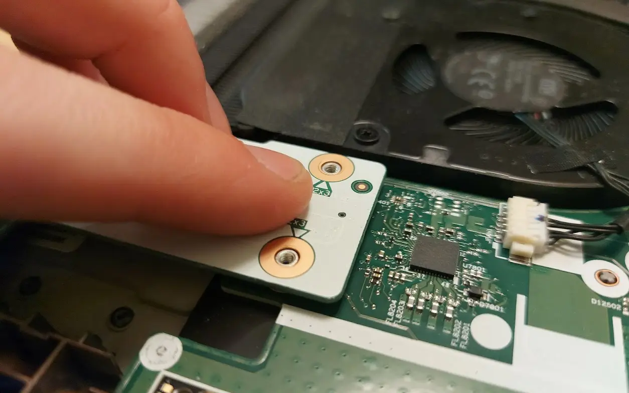
Put the new board into the laptop, using the screw holes as guides to position it correctly. Push the end firmly down to plug it into the motherboard.
Pushing the Side to Plug it in
Screw the USB Audio Board back in, then the metal plate, and then finally gently press the bottom panel back onto the laptop and re-tighten all of the screws. If done correctly, the new USB and 3.5 mm ports should be fully operational.